Painting installation

Inactive Publication Date: 2010-04-29
DUERR SYST GMBH
View PDF35 Cites 26 Cited by
  • Summary
  • Abstract
  • Description
  • Claims
  • Application Information

AI Technical Summary

Benefits of technology

[0053]According to the invention, the special design of the locks at the inlet and at the outlet considerably reduces the air volumes introduced through the locks so that the total air exchange is reduced, with the corresponding savings in energy and costs.

Problems solved by technology

Due to the high air flow rates required th

Method used


Image

  • Painting installation
  • Painting installation
  • Painting installation

Examples


Example

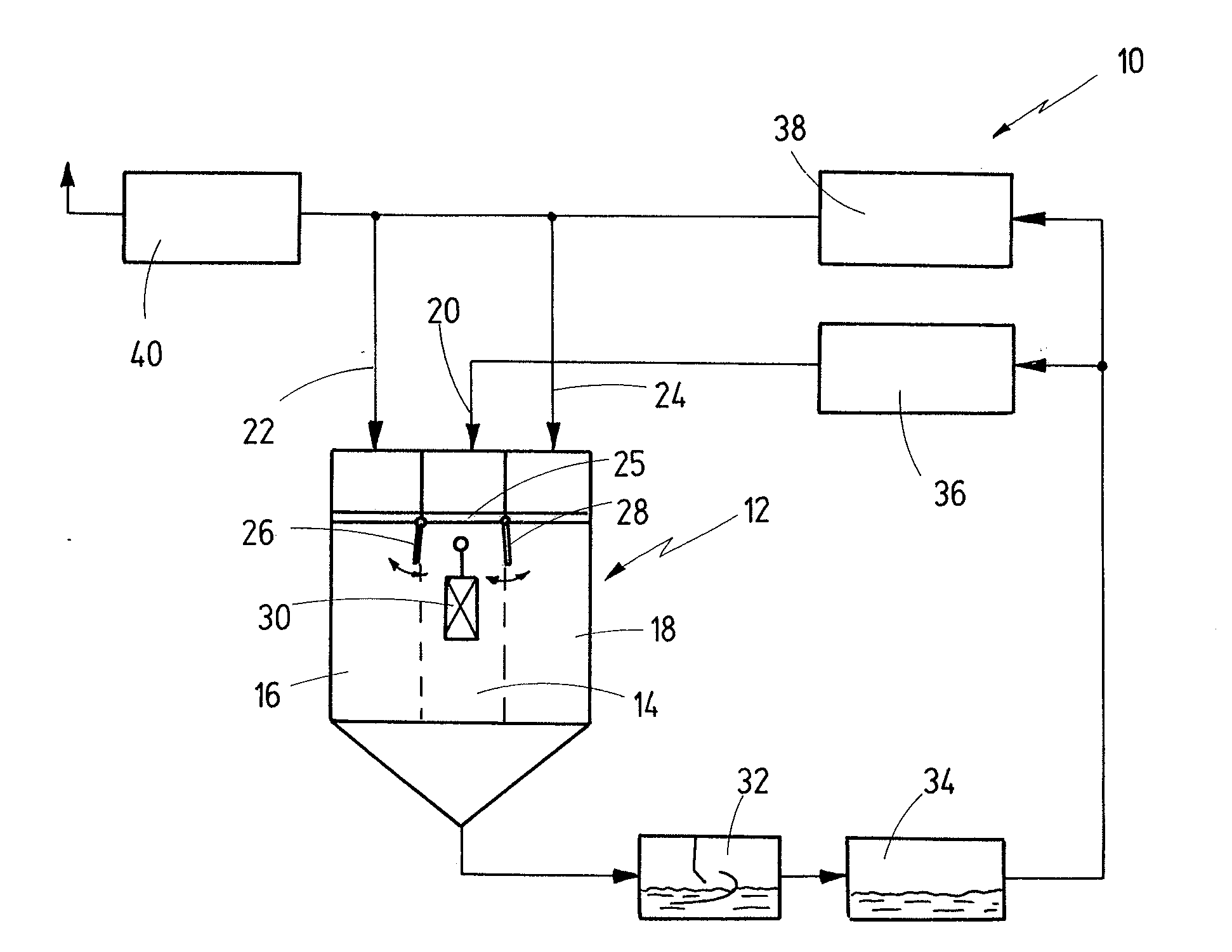
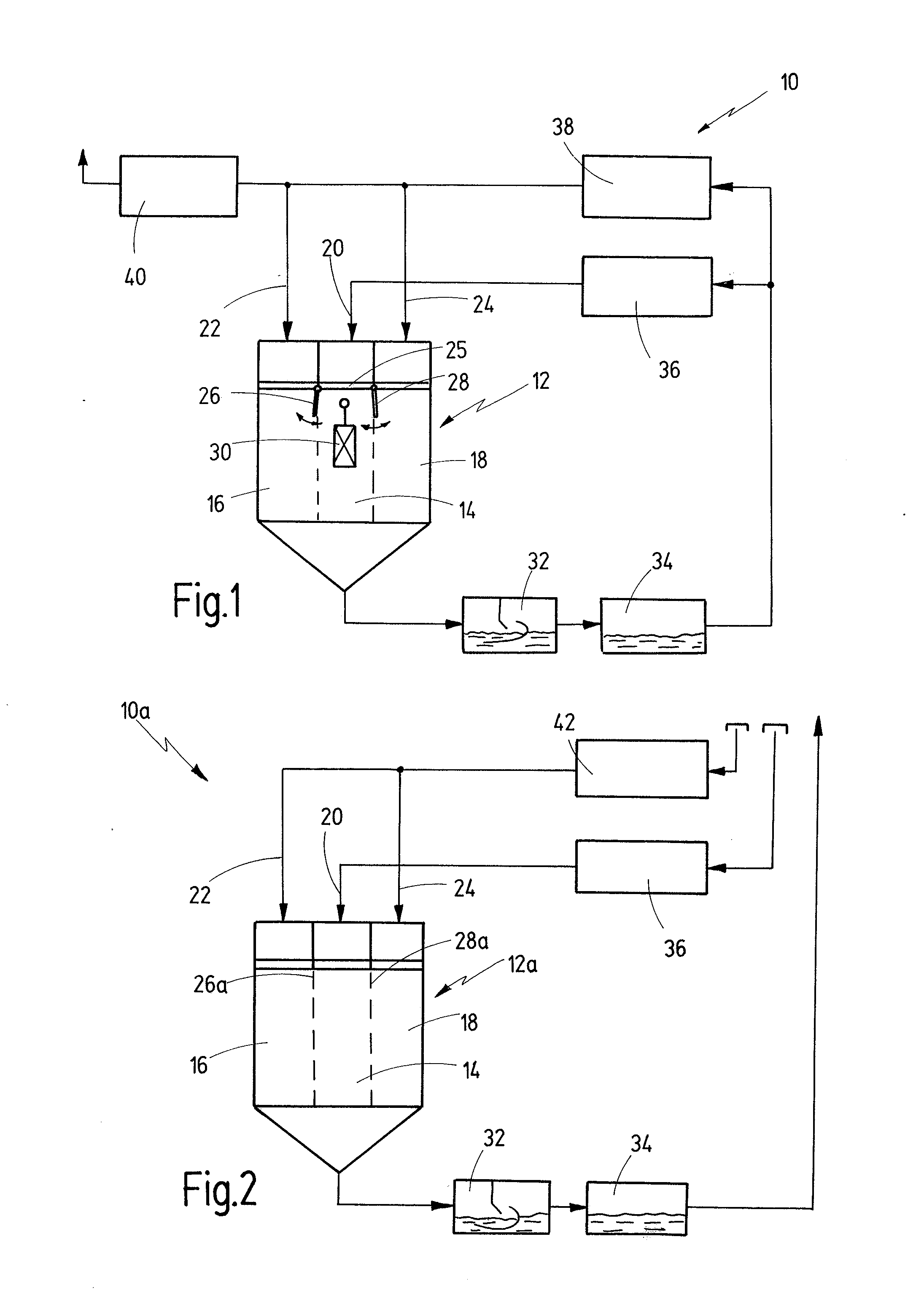
[0074]A first embodiment of the painting installation according to the invention is indicated generally by reference numeral 10 in FIG. 1.

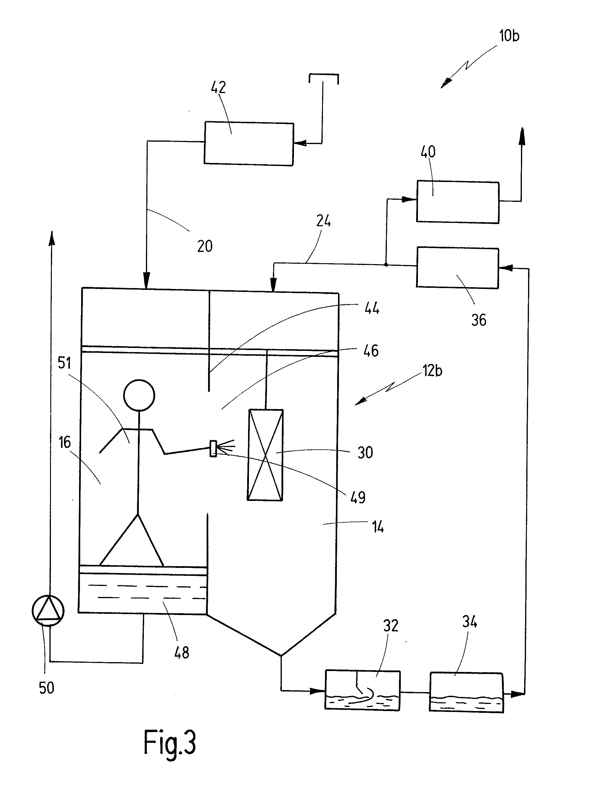
[0075]The painting installation comprises a spray booth 12, divided into three zones, namely a central application zone 14, where parts 30 are spray-coated, and two lateral auxiliary zones 16, 18 where auxiliary painting equipment, for example robots, painting appliances or the like, are arranged.

[0076]Details of the transition between the application zone 14 and the auxiliary zones 16, 18, respectively, can be seen in FIG. 4, by way of example. There is provided a first corridor 52, which extends through the spray booth 12 in lengthwise direction and through which parts 30 can be transported along a path defined by a conveyor, as indicated by arrow 54. Inside the spray booth 12 there are provided two robots 60, 62, one of them 60 located in the auxiliary zone 18, a second one 62 located in the auxiliary zone 16. Illustrated in broken lines in FIG...


PUM

PropertyMeasurementUnit
Concentrationaaaaaaaaaa
Timeaaaaaaaaaa

Abstract

The invention provides a painting installation comprising a spray booth having an application zone in which parts are to be painted, at least one auxiliary zone being separated from said application zone, an air supply and an air exhaust system having a first air supply and a second air supply, an air-conditioning device, at least one baffle element being arranged between said application zone and said at least one auxiliary zone, wherein said first air supply is provided for said application zone and is conducted via said air-conditioning device, said second air supply is provided for said auxiliary zone and is separated from said air-conditioning device, said at least one baffle element is configured for optimizing the air flow conditions in the transition area between said application zone and said auxiliary zone, wherein said exhaust air from said spray booth is recycled and at least partially fed to said air-conditioning device, and wherein said application zone is supplied only with air-conditioned air via said air-conditioning device, while said auxiliary zone is supplied with air that is not air-conditioned or only partially air-conditioned.

Description

CROSS-REFERENCES TO RELATED APPLICATIONS[0001]This application is a continuation of International Patent Application PCT / EP2008 / 001012, filed on Feb. 11, 2008 designating the U.S., which international patent application has been published in German language and claims priority from German patent application 10 2007 011 602.2, filed on Mar. 2, 2007 and from German patent application 10 2007 015 150.2, filed on Mar. 23, 2007, the entire content of which is fully incorporated by reference herewith.BACKGROUND OF THE INVENTION[0002]For high-quality spray painting results, the spray booths of spray-painting systems usually are air-conditioned. Air-conditioning requires that the air be cooled down for eliminating humidity in the air and be then heated up again to operating temperature. Due to the high air flow rates required this results in considerable air consumption.SUMMARY OF THE INVENTION[0003]In view of this it is a first object of the present invention to disclose a painting install...

Claims


Application Information

Patent Timeline
IPC IPC(8): B05B15/12F24F11/00B05B14/46B05B16/60
CPCB05B15/1222B05B16/60B05B14/46Y10S55/46Y10S118/07
Inventor WURSTER, GERD
Owner DUERR SYST GMBH
Why Eureka
Try Eureka