Planar light source apparatus
- Summary
- Abstract
- Description
- Claims
- Application Information
AI Technical Summary
Benefits of technology
Problems solved by technology
Method used
Image

Examples
first embodiment
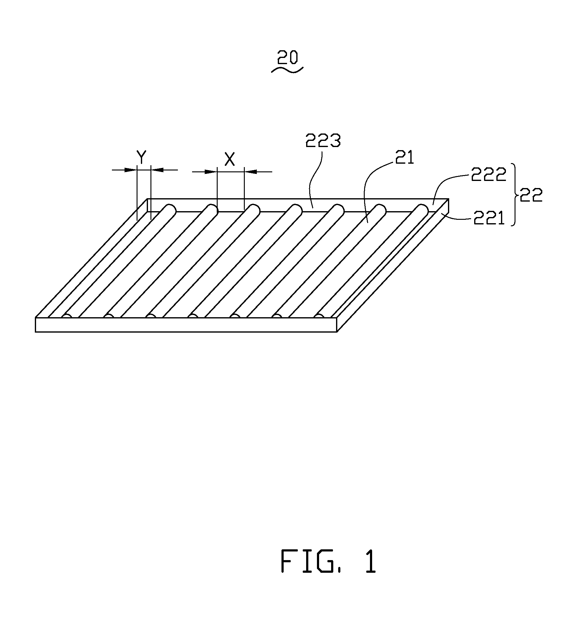
[0024]Referring to FIG. 1, an exemplary planar light source apparatus 20 in accordance with a first embodiment, is provided. The planar light source apparatus 20 is substantially rectangular, and includes a number of lighting elements 21, two first mirror reflectors 221, and two second mirror reflectors 222.
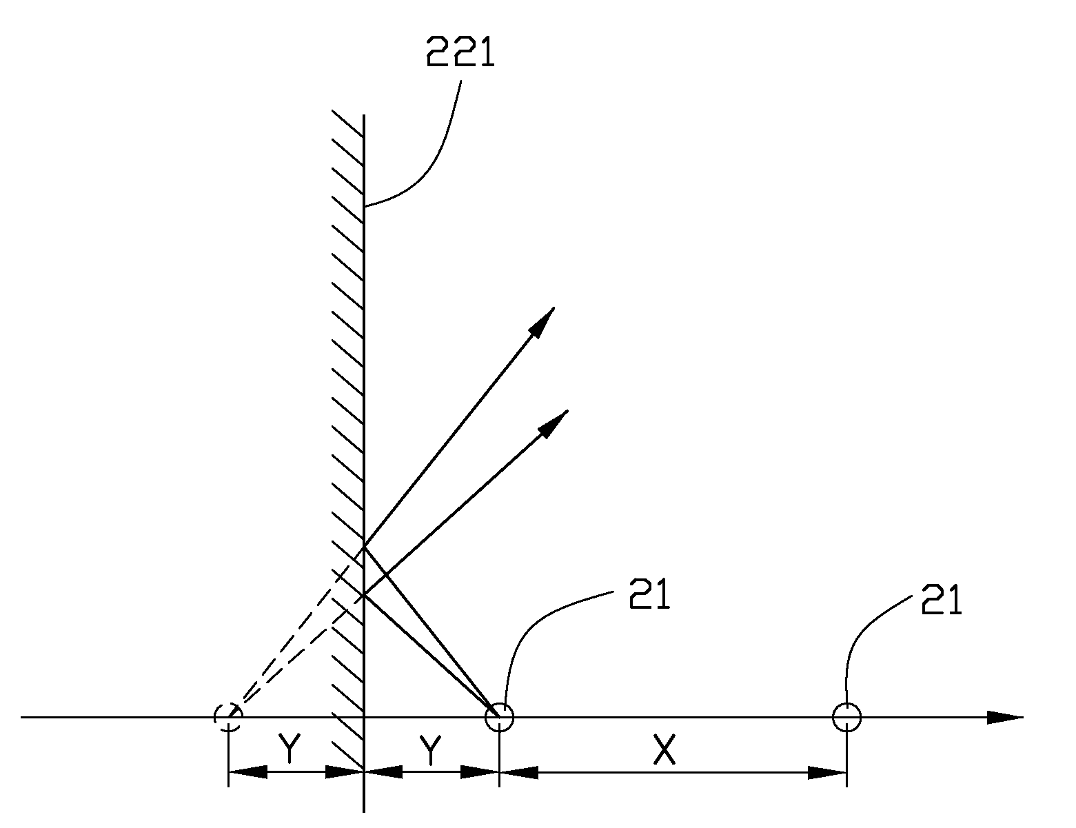
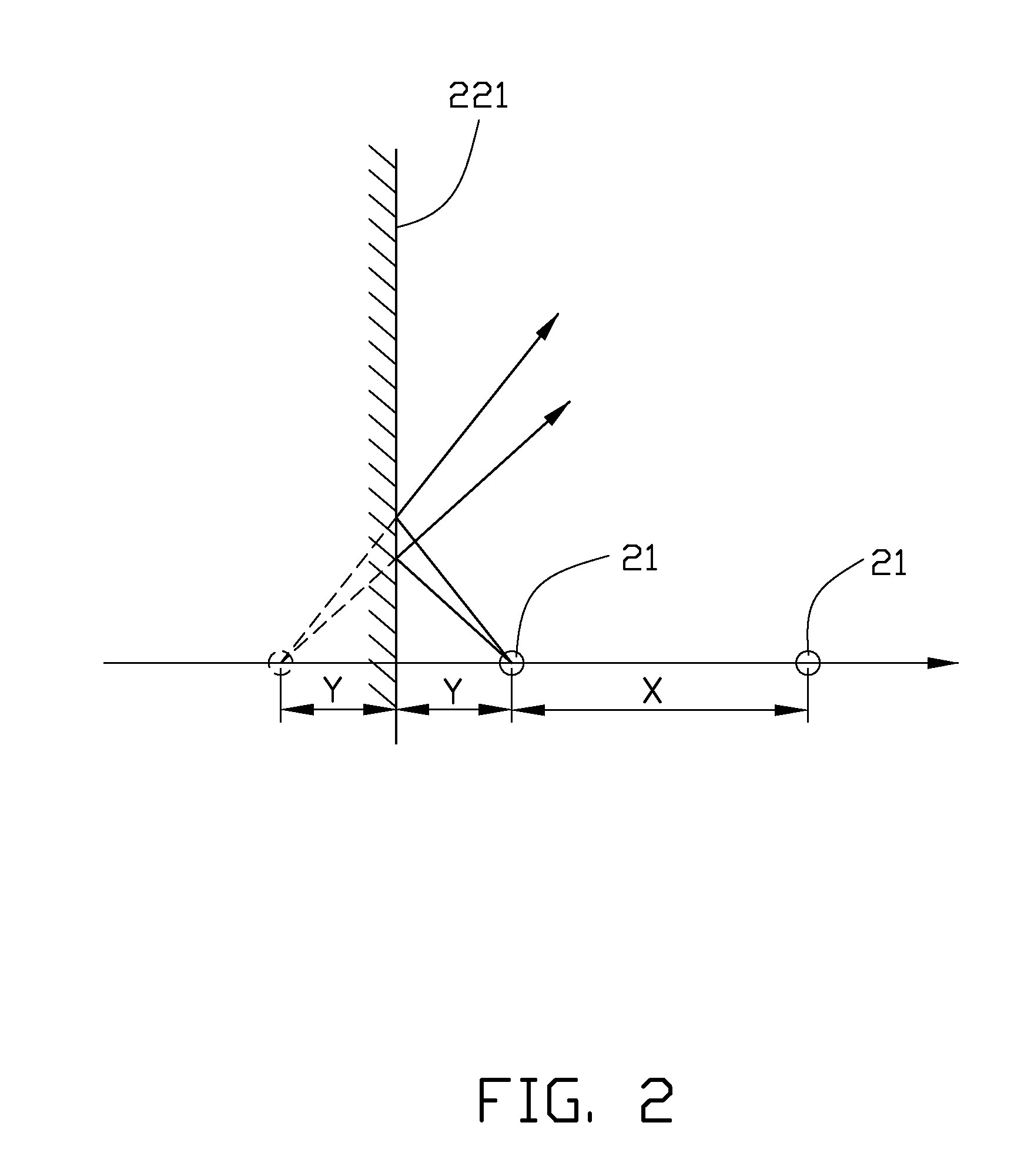
[0025]The lighting elements 21 are arranged on a same plane and equidistantly spaced from each other. The lighting elements 21 face a same direction. In the present embodiment, the lighting elements 21 are elongated shaped, and can be fluorescent lamps, cold cathode fluorescent lamps, gas discharge lamps or mercury-vapor lamps; the lighting elements 21 face the first mirror reflectors 221. Each two adjacent lighting elements 21 are a distance X apart.
[0026]The first mirror reflectors 221 and the second mirror reflectors 222 are perpendicular to the plane of the lighting elements 21. The first mirror reflectors 221 and the second mirror reflectors 222 are alternately connected end...
second embodiment
[0029]Referring to FIG. 6, an exemplary planar light source apparatus 25 in accordance with a second embodiment, is provided. The planar light source apparatus 25 is essentially similar to the planar light source apparatus 20, however, the second mirror reflectors 224 each have a number of through holes 2221 formed therein, the lighting elements 21 includes a central lighting portion 21a and two end portions 21b, the two end portions 21b of the lighting elements 21 extend through the respective through holes 2221. In this way, the second mirror reflectors 224 contact with the central lighting portion 21a, and thus the second mirror reflectors 224 contribute more to the peripheral light intensity compensation.
third embodiment
[0030]Referring to FIGS. 7 and 8, an exemplary planar light source apparatus 30 in accordance with a third embodiment, is provided. The planar light source apparatus 30 is essentially similar to the planar light source apparatus 20. However, the lighting elements 31 are generally shaped as blocks, and are equidistantly arranged in a lattice array 10×5 along the direction B and C. The lighting elements 31 can be light emitting diodes. A mirror distance Y is maintained between the first mirror reflectors 321 and the nearest lighting elements 31 facing thereto, and is maintained between the second mirror reflectors 322 and the nearest lighting elements 31 facing thereto. The lighting elements 31 are a distance X apart. The distance Y meets the condition 0≦Y≦X, preferably, 0≦Y≦X / 2 when the first mirror reflectors 321 and the second mirror reflectors 322 are metal plates. The distance Y meets the condition 0≦Y≦[X−(1+1 / n)Z] / 2 when the first mirror reflectors 321 and the second mirror refl...
PUM
 Abstract
Description
Claims
Application Information
 - R&D Engineer
- R&D Manager
- IP Professional
- Industry Leading Data Capabilities
- Powerful AI technology
- Patent DNA Extraction
Browse by: Latest US Patents, China's latest patents, Technical Efficacy Thesaurus, Application Domain, Technology Topic.
© 2024 PatSnap. All rights reserved.Legal|Privacy policy|Modern Slavery Act Transparency Statement|Sitemap