Display device and electronic timepiece

Inactive Publication Date: 2002-05-07
SEIKO EPSON CORP
View PDF8 Cites 145 Cited by
  • Summary
  • Abstract
  • Description
  • Claims
  • Application Information

AI Technical Summary

Problems solved by technology

Accordingly, the conventional electronic timepiece has a problem in that a segment portion or a background portion of the display is dark.
In addition, for the same reason, the conventional electronic timepiece has a problem

Method used


Image

  • Display device and electronic timepiece
  • Display device and electronic timepiece
  • Display device and electronic timepiece

Examples


first embodiment

[First Embodiment]

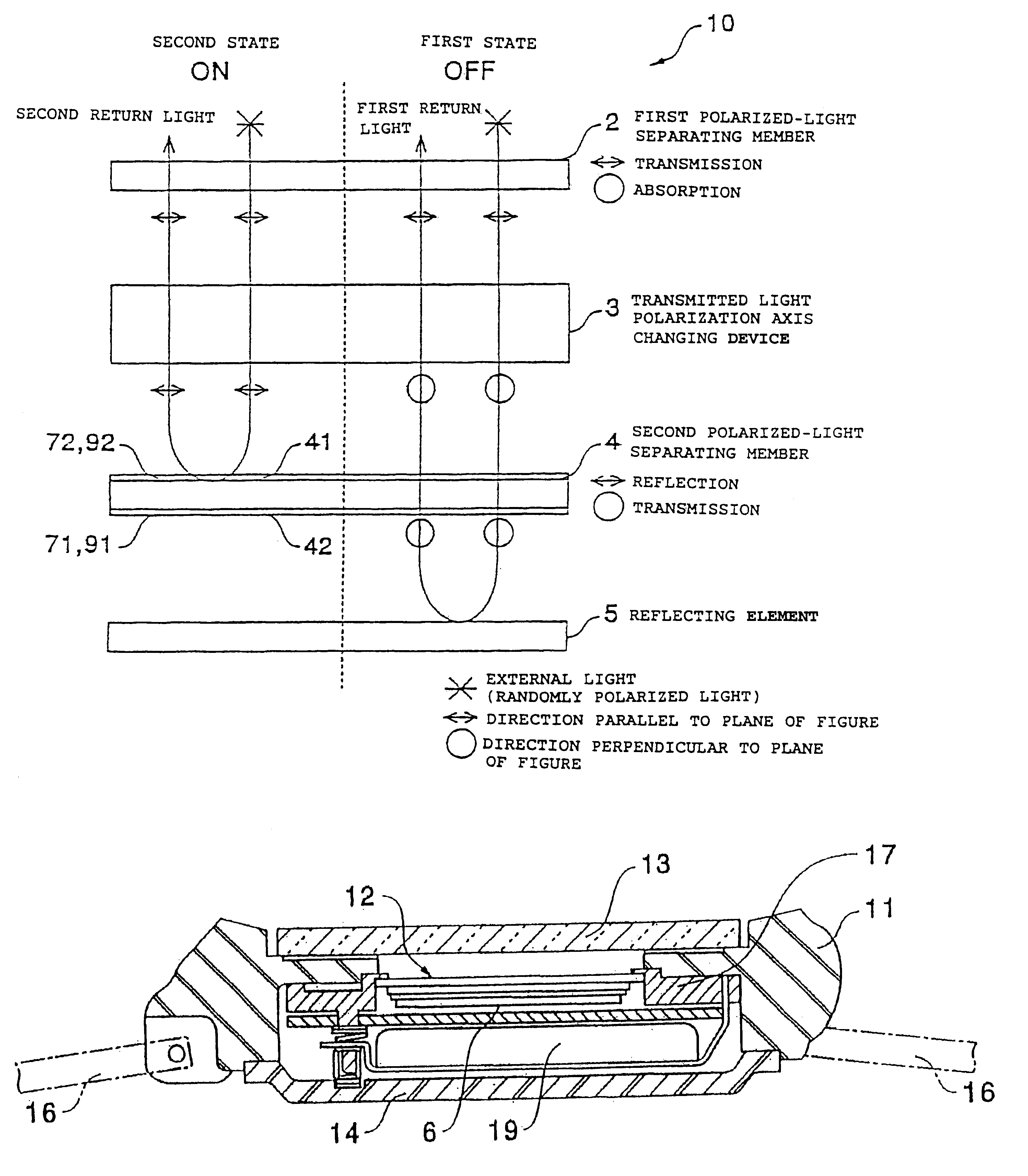
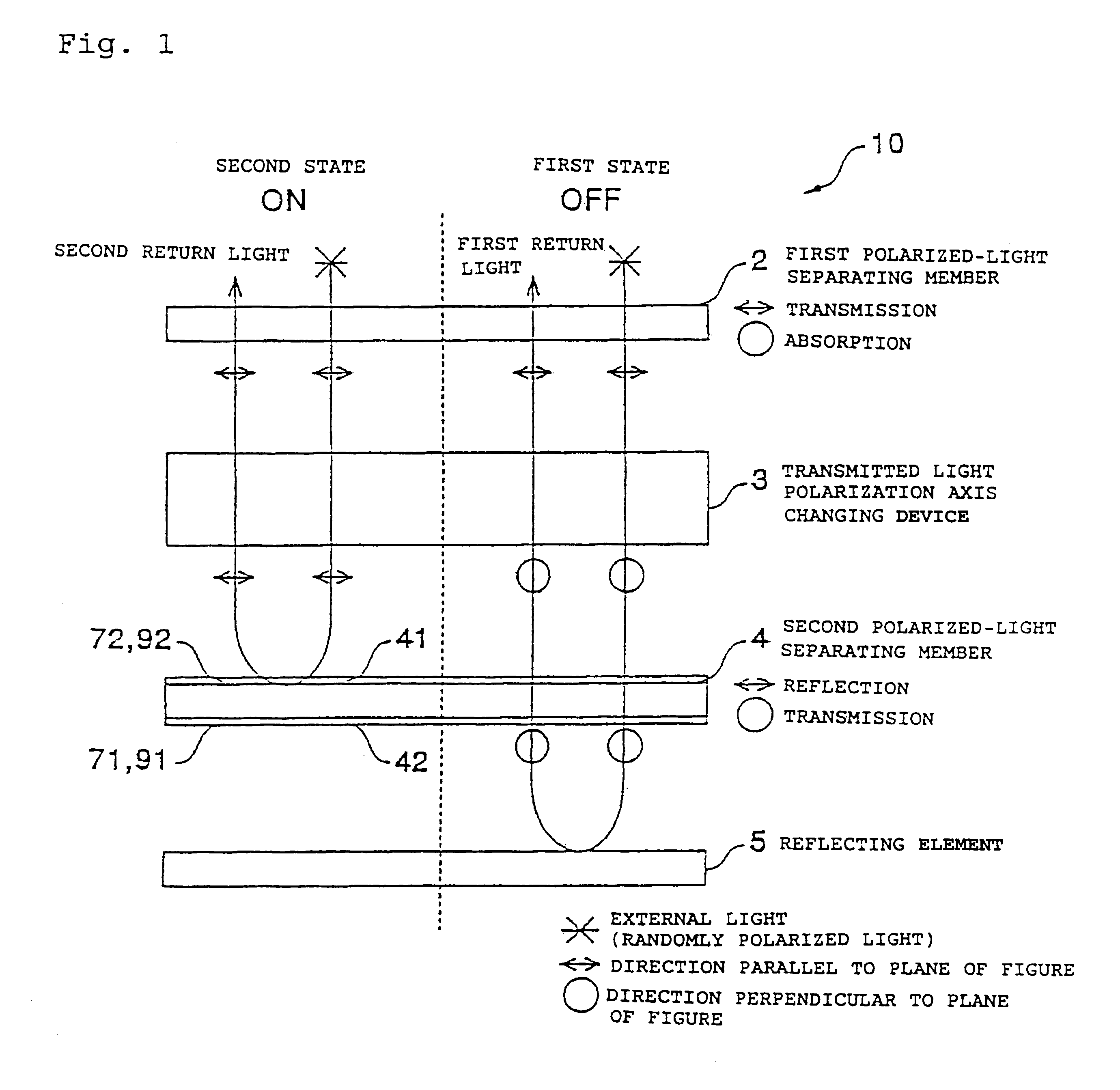
FIG. 7 is a schematic structural view of a display device according to a first embodiment of the present invention.

Referring to FIG. 7, in a display device 10 of this embodiment, a first polarized-light separating member 2 for transmitting a linearly polarized light component of incident light pointing in a first direction of incident light, a transmitted light polarization axis changing device 3 capable of selecting one of a first state of changing and a second state of not changing a transmitted light polarization axis when the incident linearly polarized light component is transmitted, a second polarized-light separating member 4 for transmitting a linearly polarized light component facing a second direction of incident linearly polarized light components and reflecting a linearly polarized light component facing a third direction intersecting perpendicularly to the second direction, and a reflecting element 5 capable of mirror-reflecting the linearly polarized ...

second embodiment

[Second Embodiment]

FIG. 8 is a schematic structural view of a display device according to a second embodiment of the present invention.

In the first embodiment 1, the segment portion equivalent to the voltage applied area (ON) in the transmitted light polarization axis changing device 3 is displayed in an achromatic mirror form. As shown in FIG. 7, however, if a surface-side coloring layer 72 is formed on a surface 41 of the second polarized-light separating member 4 facing the transmitted light polarization axis changing device 3, a segment portion is displayed in a mirror form with a hue (second hue) determined by the surface-side coloring layer 72. In this case, a background portion equivalent to the non-applied voltage (OFF) area in the transmitted light polarization axis changing device 3 is displayed in a mirror form with a composite hue of a hue imparted by a back-side coloring layer 71 and a hue imparted by the surface-side coloring layer 72.

third embodiment

[Third Embodiment]

FIG. 9 is a schematic structural view of a display device according to a third embodiment of the present invention.

As will be understood from FIG. 9, in this embodiment, a back-side light-diffusing layer 91 is formed on a back 42 facing a reflecting element 5 of a second polarized-light separating member 4, and unlike in the first and second embodiments, no coloring layers are formed. With this construction, a segment portion is displayed in an achromatic mirror form. In contrast, in a background area, while a linearly polarized light component is being transmitted by the second polarized-light separating member 4, a transmitted light polarization axis changing device 3, and a first polarized-light separating member 2 after being transmitted by the second polarized-light separating member 4 and mirror-reflected by the reflecting element 5, the linearly polarized light component is subjected to light diffusion by the back-side light-diffusing layer 91 of the second ...


PUM


Abstract

A display device is provided which is able to effect high visibility display utilizing external light, and which is able to effect reflective display with a combination of various textures and color. The display device includes a first polarized-light separating member for transmitting a linearly polarized light component polarized in a first direction, a transmitted light polarization axis changing device capable of selecting states of changing and not changing a transmitted light polarization axis, a second polarized-light separating member for transmitting a linearly polarized light component in a polarized second direction and for mirror-reflecting a linearly polarized light perpendicular to the linearly polarized light component, and a reflecting element disposed in that order. Coloring layers or light-diffusing layers are formed on the surface or the back of the second polarized-light separating member.

Description

1. Field of the InventionThe present invention relates to display devices for displaying characters, numerals, patterns and so forth. In addition, the present invention relates to electronic timepieces, such as wristwatches, stopwatches and so forth using the display devices. More specifically, the present invention relates to a display technology such as a liquid crystal device for displaying information by selecting one of the states of changing and not changing of a transmitted light polarization axis of a trasmitted linearly polarized light component.2. Description of the Related ArtAs a device for effecting display using external light, a digital-display-type timepiece using a liquid crystal device is most common. As such an electronic timepiece, one is conventionally known in which a first polarizer, a trasmitted light polarization axis changing optical element (transmitted light polarization axis changing means), such as a liquid crystal device, capable of selecting one of th...

Claims


Application Information

Patent Timeline
IPC IPC(8): G02F1/13G02F1/1335G04G9/00
CPCG02F1/133514G02F1/133536G04G9/0035G02F1/133555G02F2001/133545G02F2203/02G02F1/133545
Inventor ARIKAWA, YASUOMATSUI, TSUYOSHI
Owner SEIKO EPSON CORP
Why Eureka
Try Eureka