Display device for exterior rearview mirror

a technology for rearview mirrors and display devices, applied in the field of exterior rearview mirror assemblies, can solve problems such as difficulty for the driver of the host vehicle to determin

Inactive Publication Date: 2010-08-17
DONNELLY CORP
View PDF85 Cites 148 Cited by
  • Summary
  • Abstract
  • Description
  • Claims
  • Application Information

AI Technical Summary

Benefits of technology

[0008]According to an aspect of the present invention, an exterior rearview mirror assembly for a vehicle includes a mirror reflective element, a mirror reflective element sub-assembly for an exterior rearview mirror assembly of a vehicle includes a mirror reflective element and a video display element disposed behind the mirror reflective element so that images displayed by the video display element are viewable through the mirror reflective element when the video display element is activated. The video display element is configured to display images that are readily viewable by the driver of the host vehicle and not readily viewable by drivers of other vehicles in the lane adjacent to the host vehicle. Optionally, the video display element may be operable to display other images that are readily viewable by drivers of other vehicles in the lane adjacent to the host vehicle and not readily viewable by the driver of the host vehicle.

Problems solved by technology

It is known to provide an object in a blind spot detection / LCA system for a vehicle that detects the presence of another vehicle or object in the lane next to the host vehicle, where it may be difficult for the driver of the host vehicle to determine whether or not there is another vehicle or object adjacent to the host vehicle.

Method used


Image

  • Display device for exterior rearview mirror
  • Display device for exterior rearview mirror
  • Display device for exterior rearview mirror

Examples


Embodiment Construction

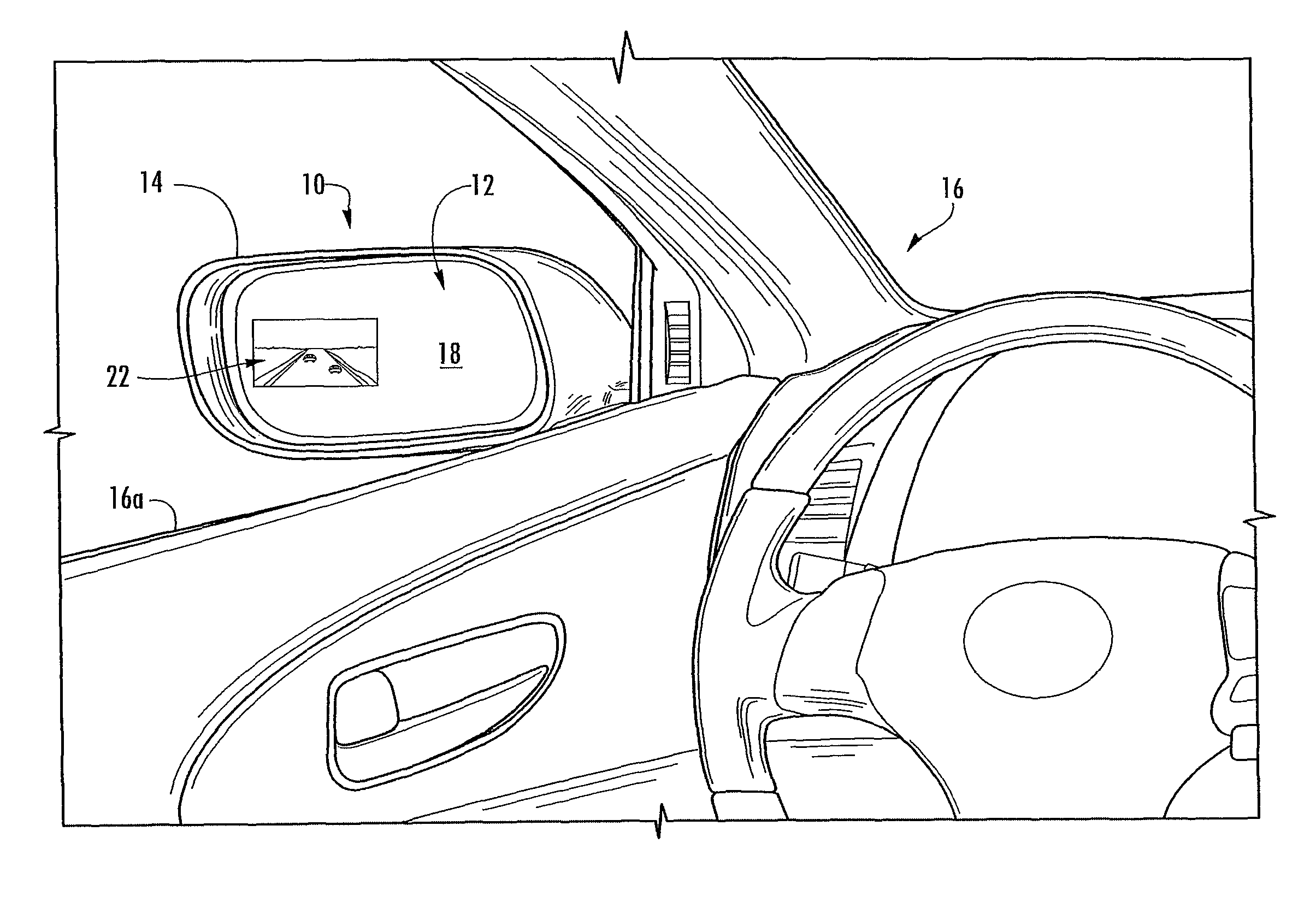
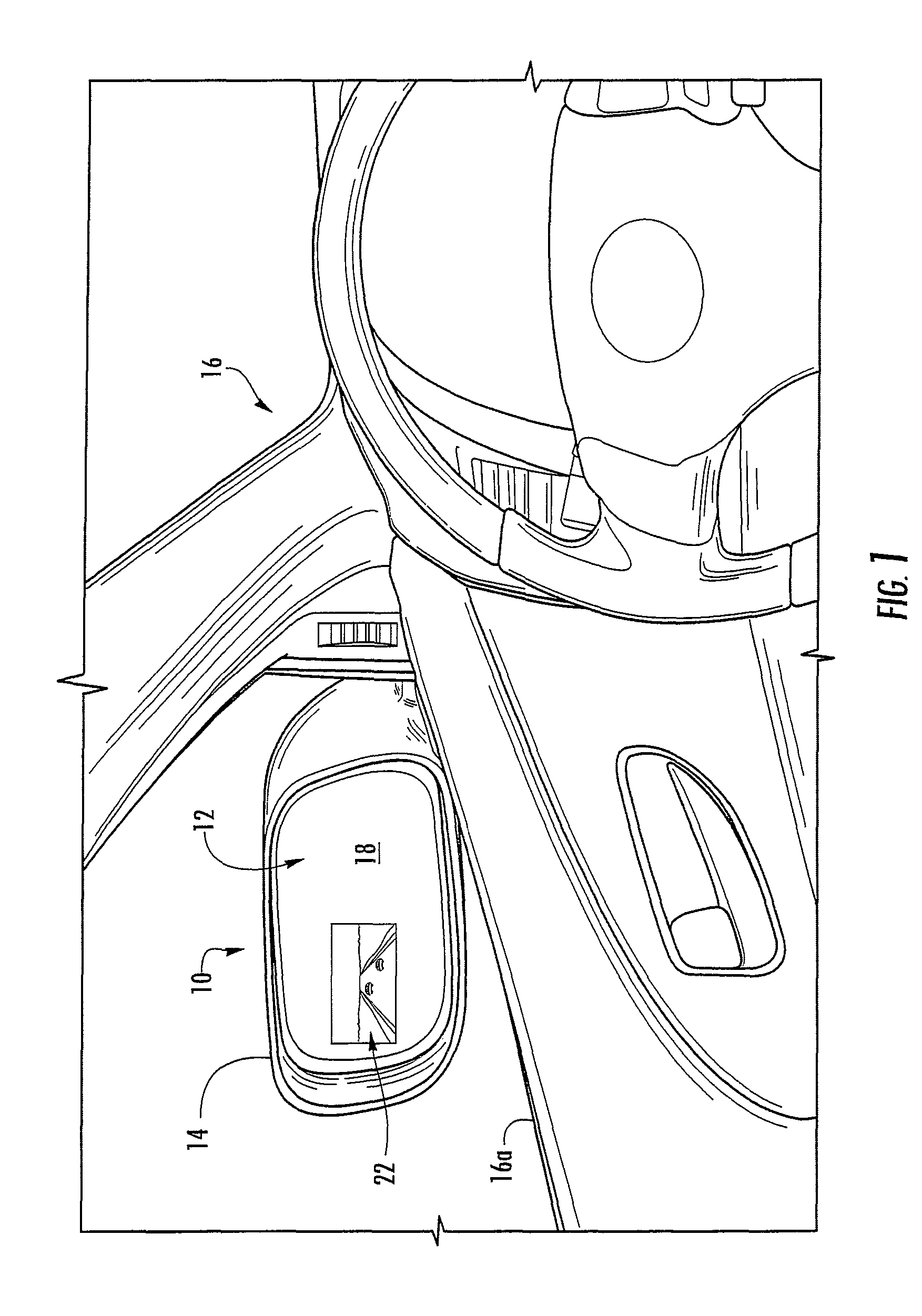
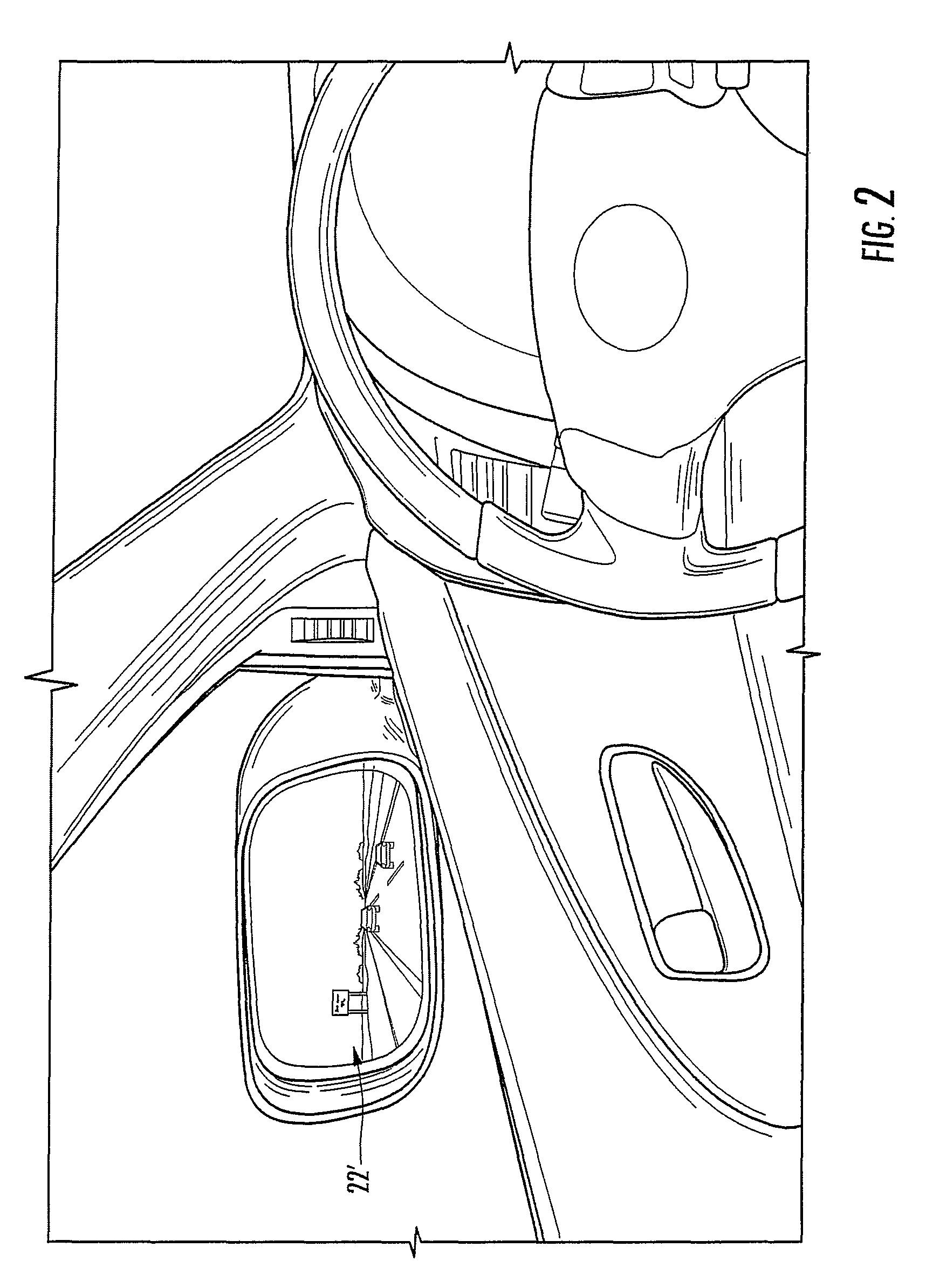
[0013]Referring now to the drawings and the illustrative embodiments depicted therein, an exterior rearview mirror assembly 10 for a vehicle includes a mirror reflector sub-assembly 12 and a mirror shell or casing 14 (FIG. 1). Mirror assembly 10 is mounted at the side 16a of a host or subject vehicle 16. Mirror assembly 10 includes a display element or device 22 that is disposed behind reflective element 18 and that is operable to provide a display or indication at the reflective element for viewing the display or indication through the mirror reflective element. The display device 22 comprises a video display device or module that may be actuatable in response to a blind spot detection / lane change assist system detecting an object at the side of the vehicle and in the area that is typically referred to as the “blind spot”, so that the driver is able to view the images of the blind spot to see what was detected by the blind spot detection system, as discussed below.

[0014]Display dev...


PUM


Abstract

A mirror reflective element sub-assembly for an exterior rearview mirror assembly of a vehicle includes a mirror reflective element and a video display element. The video display element is disposed behind the mirror reflective element so that images displayed by the video display element are viewable through the mirror reflective element when the video display element is activated. The video display element is configured to display images that are readily viewable by the driver of the host vehicle and not readily viewable by drivers of other vehicles in the lane adjacent to the host vehicle.

Description

CROSS REFERENCE TO RELATED APPLICATION[0001]The present application claims benefit of U.S. provisional application Ser. No. 60 / 857,025, filed Nov. 6, 2006, which is hereby incorporated herein by reference in its entirety.FIELD OF THE INVENTION[0002]The present invention relates to exterior rearview mirror assemblies and, more particularly, to an exterior rearview mirror assembly having a turn signal indicator or a blind spot / object detection indicator and / or a lane change aid (LCA) indicator or other indicator at the exterior rearview mirror assembly.BACKGROUND OF THE INVENTION[0003]It is known to provide an object in a blind spot detection / LCA system for a vehicle that detects the presence of another vehicle or object in the lane next to the host vehicle, where it may be difficult for the driver of the host vehicle to determine whether or not there is another vehicle or object adjacent to the host vehicle. Such an object in a blind spot detection / LCA system often includes a visual ...

Claims


Application Information

Patent Timeline
Patent Type & Authority Patents(United States)
IPC IPC(8): B60Q1/00
CPCB60Q1/2665B60Q9/00B60R2001/1253B60R1/06B60R1/1207B60R2001/1223
Inventor DESAI, DEVAL M.
Owner DONNELLY CORP
Why Eureka
Try Eureka