
Cable management device

Inactive Publication Date: 2010-05-06
COMMSCOPE TECH LLC +1
View PDF8 Cites 9 Cited by
  • Summary
  • Abstract
  • Description
  • Claims
  • Application Information

AI Technical Summary

Problems solved by technology

This may be undesirable, for example making it difficult to visually trace the paths of individual cables.
This is however time consuming and may result in damage to the cables due to the thread embedding into the cable.
Also, subsequent lengthwise adjusting the position of individual cables is difficult or impossible.

Method used


Image

  • Cable management device
  • Cable management device
  • Cable management device

Examples


Embodiment Construction

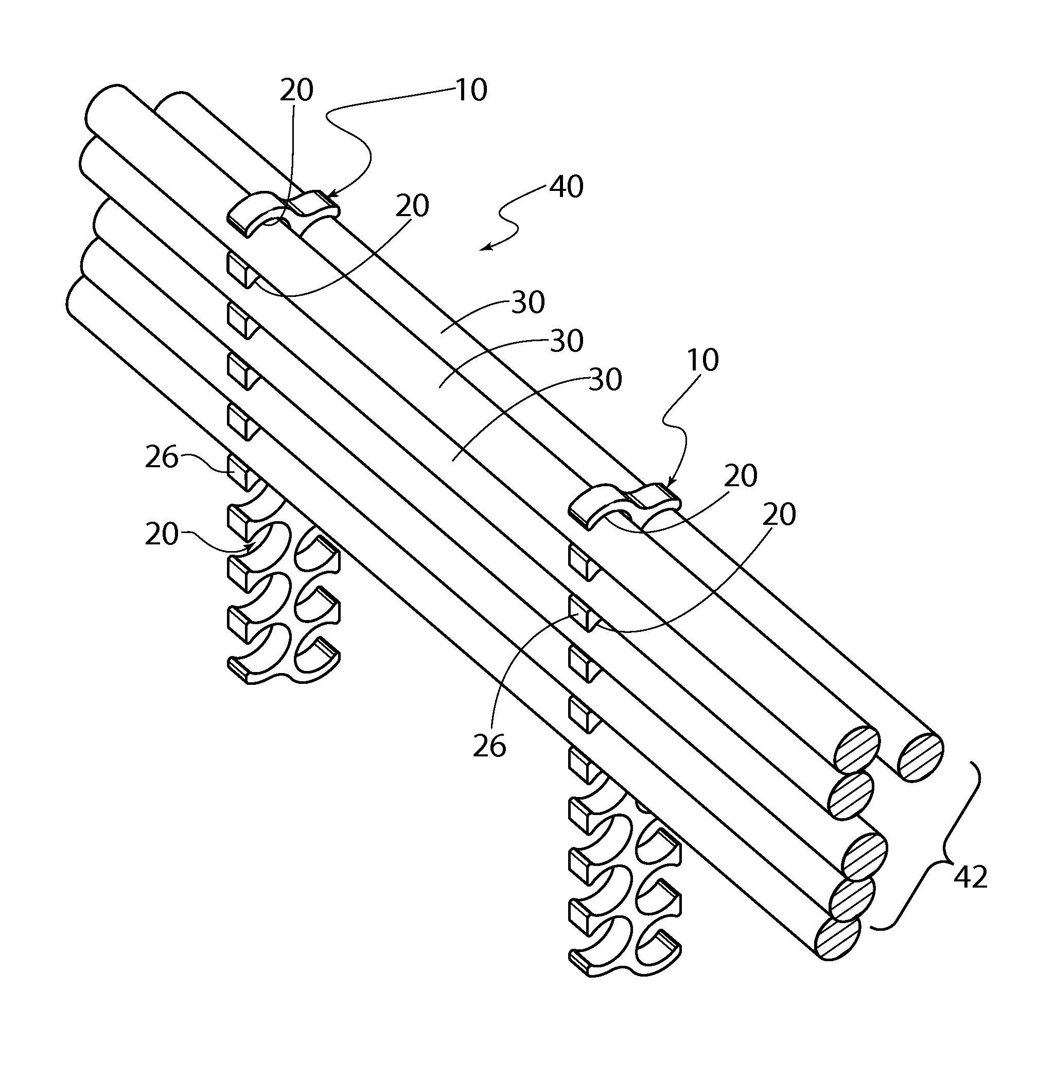
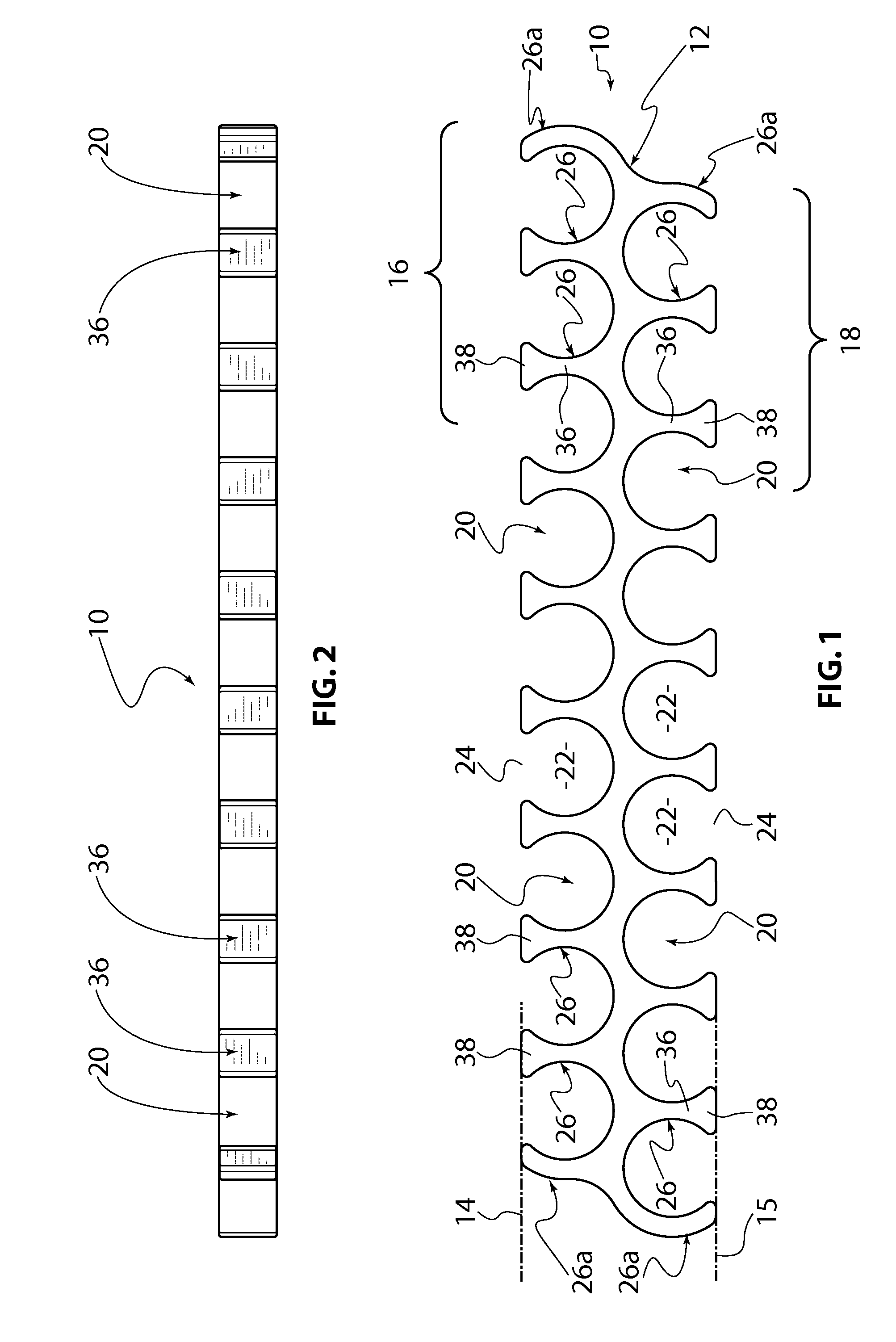
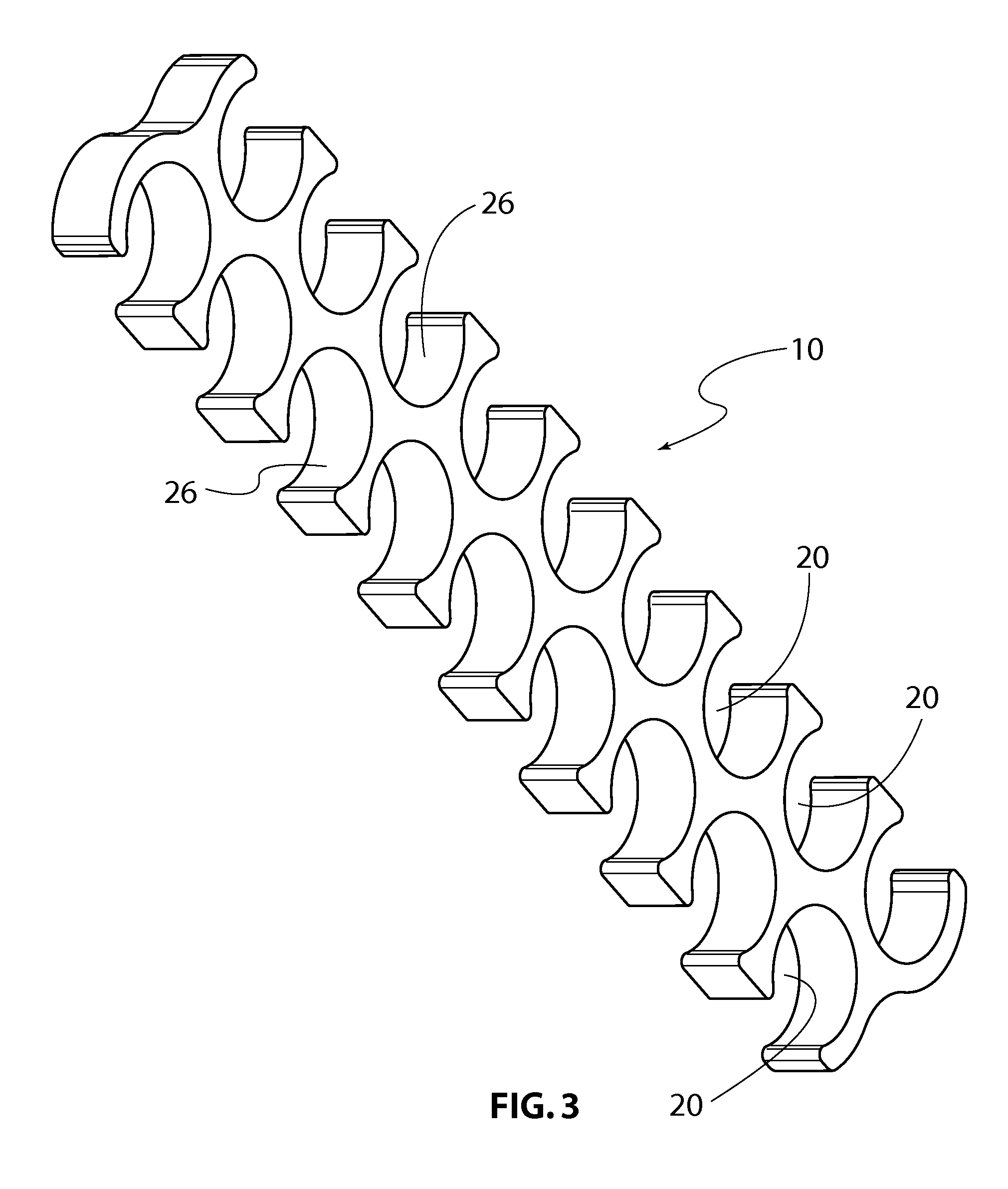
[0018]The cable management device 10 shown is in the form of a plastics moulding having a flat elongate generally rectangular body 12. At each of two opposed longer sides, 14, 15, the body 12 has a respective row 16, 18 of cable retaining cavities 20. The cavities 20 have a part circular cable retaining portion 22, and a relatively narrow entrance portion 24 open to the respective side 14 or 15 of the body. The entrance portions 24 are defined between tongue-like portions 26 of body 12. Except for end ones of the portions 26, these are between adjacent ones of the cavities 20 in each row 16, 18. As shown, except for end ones, each portion 16 has an outstanding part 36 and at the outer end thereof, a sidewardly enlarged head part 38. The end tongue-like portions 26a only define curved tongue-like projections.

[0019]FIGS. 5 to 8 illustrate the manner in which a cable 30 is inserted into a cavity 20 of the device 10. As shown, the cable 30 is advanced to the device 10 so as to approach ...


PUM


Abstract

The invention relates to a cable organization device (10) with a body (12) formed of resilient material. The body comprises cavities for holding the cables (20). Each cavity (20) comprises a cable holding section (22) for accommodating a cable, and a relatively small input section (24). The cable can be introduced in the respective cavity (20) through the input section in that the input section is opened with resilient deformation by the sections (26) of the cable defining the input section.

Description

FIELD OF THE INVENTION[0001]This invention relates to a cable management device.BACKGROUND OF THE INVENTION[0002]For ease of handling, cables such as telecommunications cables may be tied in a bundle by use of flexible plastic ties having an elongate tongue portion with an eye at one end, through which eye the other end of the tongue portion may be threaded, to form a loop around the cables, cooperating latching formations on the eye and tongue portion engaging to prevent the loop from being released. This generally results in the bundle of cables assuming a round shape when viewed in cross-section. This may be undesirable, for example making it difficult to visually trace the paths of individual cables. Another technique is to lace the cables using fine thread, such as nylon thread. This is however time consuming and may result in damage to the cables due to the thread embedding into the cable. Also, subsequent lengthwise adjusting the position of individual cables is difficult or ...

Claims


Application Information

Patent Timeline
IPC IPC(8): F16L3/22
CPCH02G3/30
Inventor PATCHETT, LEONARD JAMESLEE, SCOTT DAVID
Owner COMMSCOPE TECH LLC
Learn More