Patch panel for fiber optic network

a fiber optic network and patch panel technology, applied in the direction of coupling device details, coupling device connections, instruments, etc., can solve the problems of inconvenient installation of cassettes, inconvenient installation of rails in existing enclosures,

Active Publication Date: 2008-07-29
ORTRONICS INC
View PDF1 Cites 126 Cited by
  • Summary
  • Abstract
  • Description
  • Claims
  • Application Information

AI Technical Summary

Problems solved by technology

Therefore, the rail locations in the existing enclosures are not optimally located to accommodate suitable fiber optic bend radii.
In the same vain, the designers of these existing enclosures have not accounted for any installation of cassettes (e.g., a modular fiber optic system) within these enclosures.

Method used


Image

  • Patch panel for fiber optic network
  • Patch panel for fiber optic network
  • Patch panel for fiber optic network

Examples


Embodiment Construction

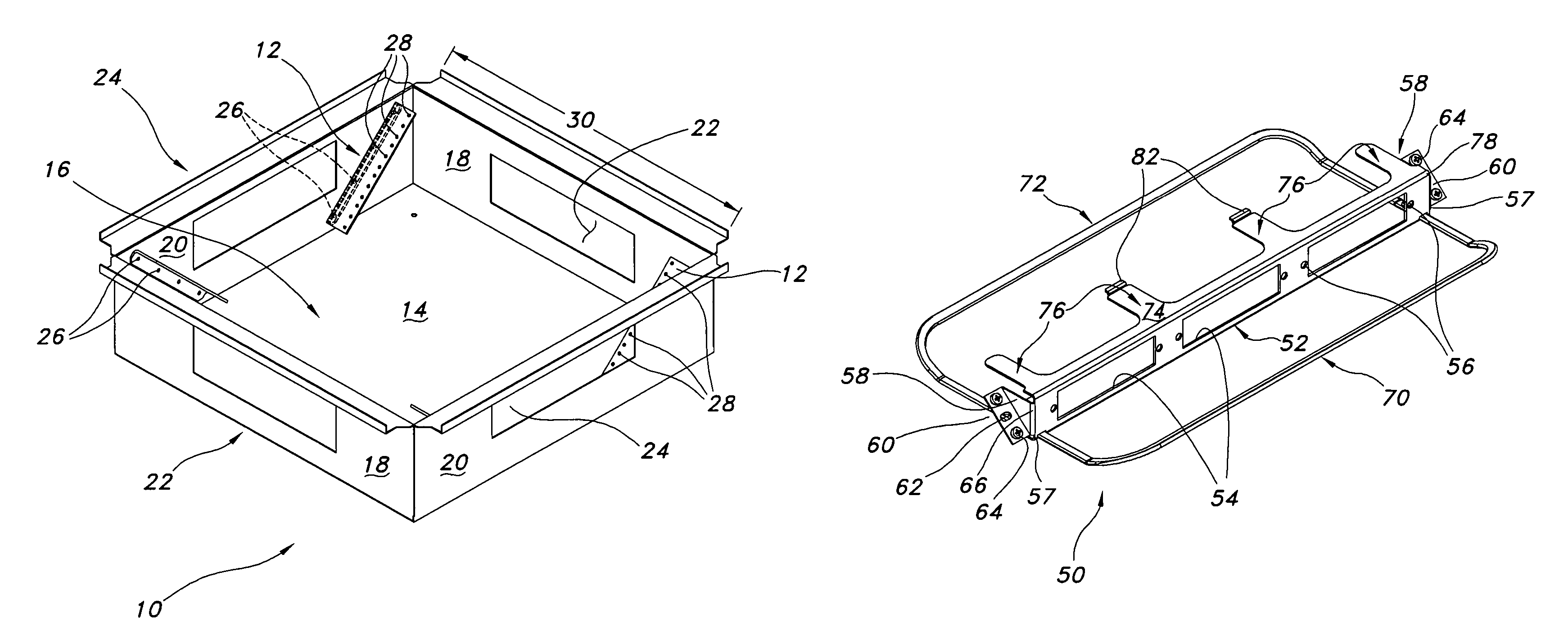
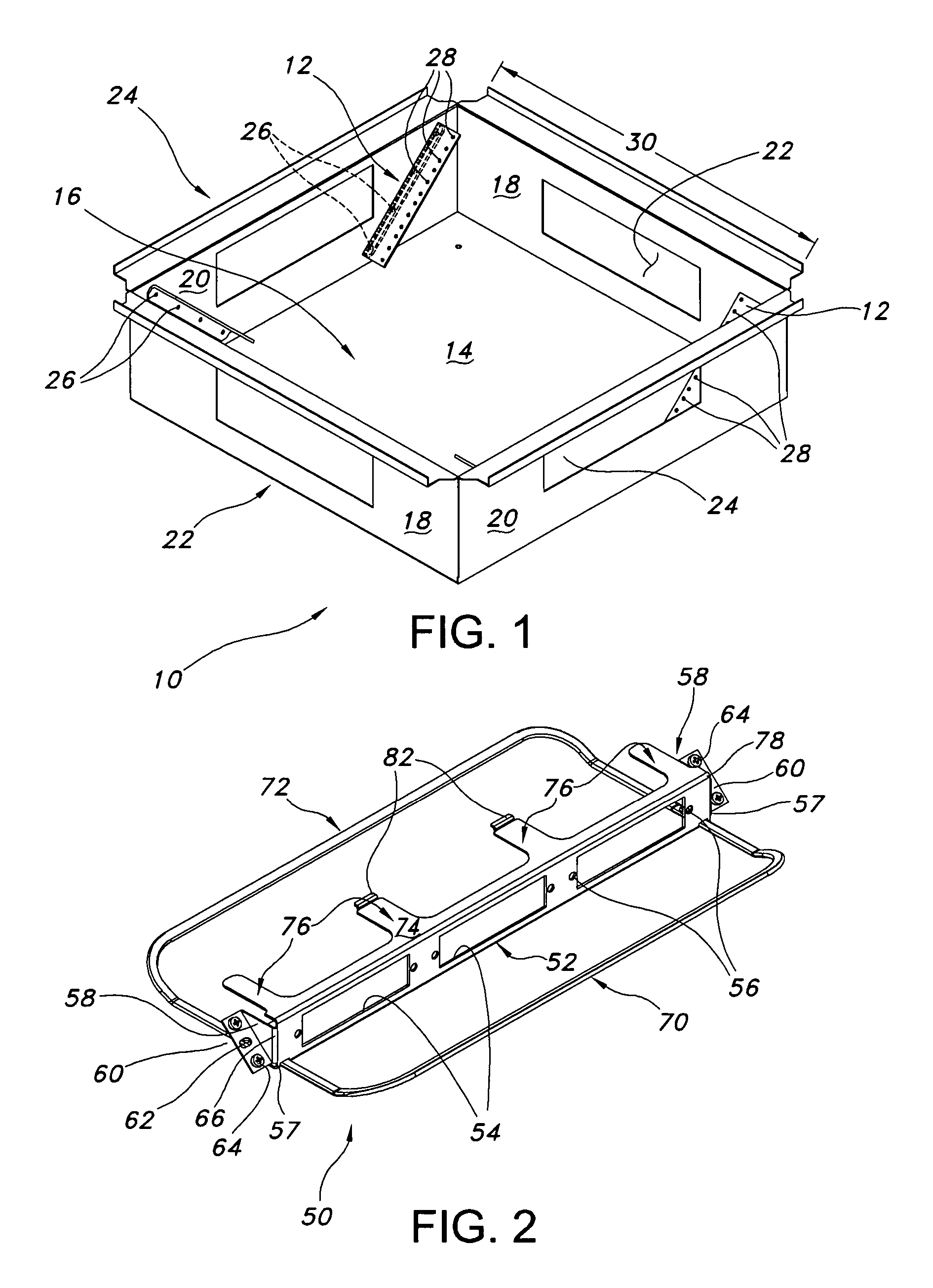
[0017]FIG. 1 illustrates a conventional raised floor enclosure 10, which can be installed in a standard floor tile footprint. In one embodiment, enclosure 10 includes a 2 foot by 2 foot opening 16 defined by two opposing trunk walls 18 and two opposing patch walls 20. Each trunk wall 18 defines a trunk opening 22, while each patch wall 20 defines a patch opening 24. The trunk wall openings 22 allow fiber optic cables into enclosure 10 for connection therein, while patch wall openings 24 allow fiber optic cables to exit enclosure 10 after connection within enclosure 10. As illustrated in FIG. 1, two pairs of mounting rails 12 are angularly or obliquely disposed (relative to bottom wall 14) on opposing patch walls 24. Rails 12 are mounted to walls 20 using fasteners 26, such as rivets or screws, for example. Each rail 12 includes a plurality of spaced apart mounting holes 28 along a length defining each rail 12. The rails 12 are inclined at angles ranging from 45-60 degrees from the f...


PUM


Abstract

The present disclosure is related to an apparatus and method that enables fiber optic network installers to mount fiber optic connections in raised floor locations that would otherwise be unsuited to the task. The method and apparatus permit using a de facto standard raised floor enclosures to accommodate fiber optic connections while maintaining bend radius considerations. In an exemplary embodiment, a patch panel includes a panel face defined by a bottom edge, a top edge and opposing side edges each joined to the bottom and top edges; a cable management bar operably coupled to the panel face, spaced apart from at least one surface side defining the panel face and extending a substantial length defining a length of the panel face; and a pair of mounting brackets extending from the opposing side edges. Each mounting bracket includes a mounting plane aligned with a plane of a corresponding angled mounted rail for mounting thereto such that the panel face is perpendicular to a bottom wall defining the enclosure in which it is mounted.

Description

TECHNICAL FIELD[0001]The present disclosure is directed generally to a patch panel for a fiber optic network and, more particularly, to a raised floor patch panel for use with prior art raised floor enclosure designs to accommodate fiber optic connections while maintaining a suitable bend radii of the fiber optic cables within the raised floor panel enclosure.BACKGROUND OF THE INVENTION[0002]It is sometimes necessary to patch communication cables within the floor or ceiling space in data centers, storage area networks (SAN) and local area networks (LAN). Patch panels and like cabinetry (e.g., enclosures) are widely employed in communication systems to facilitate such connections along various distribution paths of a network.[0003]Floor spaces are typically low profile and fire codes require that the enclosures create isolation between the plenum air space and the cable interconnect point. This isolation, or fire stop, prevents any burning of connectivity components from making the p...

Claims


Application Information

Patent Timeline
Patent Type & Authority Patents(United States)
IPC IPC(8): G02B6/00
CPCG02B6/4466H02G3/385H01R13/518G02B6/475
Inventor MURANO, ADAM
Owner ORTRONICS INC
Why Eureka
Try Eureka