Propeller MRI with phase correction

a technology of phase correction and propeller, which is applied in the field of magnetic resonance imaging devices, can solve the problems of affecting the accuracy of image artifacts, the phase information of acquired mr signals is mostly lost, and the general truth of acquired mr signals in image space, so as to achieve the effect of avoiding image artifacts and reducing image artifacts

Active Publication Date: 2010-05-13
KONINKLIJKE PHILIPS ELECTRONICS NV
View PDF10 Cites 19 Cited by
  • Summary
  • Abstract
  • Description
  • Claims
  • Application Information

AI Technical Summary

Benefits of technology

[0014]The essential feature of the invention is the computation of phase errors from the phase differences of two or more k-space blades having different rotation angles and the corresponding correction of the phases of the MR signals. The phase errors may be computed in image space, equivalent calculations may be performed in k-space or in a hybrid space. Phase errors due to the gradient system of the MR device can be removed in this way while preserving the complete phase information of the MR signals. Hence, the technique of the invention enables the reconstruction of complex MR images (including real, imaginary or phase images) from the MR signal data set acquired using PROPELLER and avoids image artifacts arising from the removal of most phase information as in the known PROPELLER concept.
[0015]Preferably, the MR device of the invention is further arranged to compute the phase errors from the phase differences of pairs of k-space blades having (nearly or exactly) opposed rotation angles. The phase errors of the MR data from k-space blades having a difference in the rotation angle of 180° are identical except for their signs, since the readout magnetic field gradients reverse their polarity. It is thus a straightforward computation to determine the phase errors for pairs of k-space blades having opposed readout directions. However, the technique of the invention does not require additional scan time, since an exact 180° difference in rotation angle of the k-space blades is not required to extract the phase errors with sufficient precision. A re-acquisition of k-space samples is not necessary to practically execute the technique of the invention. Preferably, adjacent k-space blades are acquired according to the invention with nearly or exactly opposed readout and / or preparation directions.
[0016]According to a further preferred embodiment of the invention, the MR device may be arranged to compute amplitude errors from the amplitude differences of two or more k-space blades having different rotation angles. These calculations may be performed in image space or by equivalent calculations in k-space or a hybrid space. Image artifacts can be further reduced in this way.
[0018]According to a further preferred embodiment of the invention, the MR imaging sequence applied for PROPELLER acquisition is a BFFE or an IR sequence. Both in BFFE and in IR imaging, large local phase variations may occur, due to different relaxation time constants or field inhomogeneity. These lead to substantial artifacts in magnitude images if the phase information is largely removed, as by the conventional PROPELLER phase correction. In contrast, the invention allows the use of BFFE or IR sequences for PROPELLER acquisitions, because it preserves the phase information of the acquired MR signals and thus avoids these artifacts. For the same reason, the invention is advantageous for phase-contrast acquisitions and for gradient echo imaging in the presence of chemical shift, as in non-selective water and fat acquisitions.

Problems solved by technology

This is generally not exactly true due to imperfections of the switched magnetic field gradients.
These imperfections mainly result in phase errors of the acquired MR signals in image space.
A drawback of the conventional PROPELLER concept is that phase information of the acquired MR signals is mostly lost during the above-described phase correction procedure.
This renders it impossible to reconstruct complex MR images, as it is required or at least desired for a lot of MR acquisition methods, such as, e.g., Inversion Recovery (IR).
Moreover, the conventional approach gives rise to severe artifacts in magnitude MR images using certain MR acquisition methods, such as IR and Balanced Fast Field Echo (BFFE) sequences.

Method used


Image

  • Propeller MRI with phase correction
  • Propeller MRI with phase correction
  • Propeller MRI with phase correction

Examples


Embodiment Construction

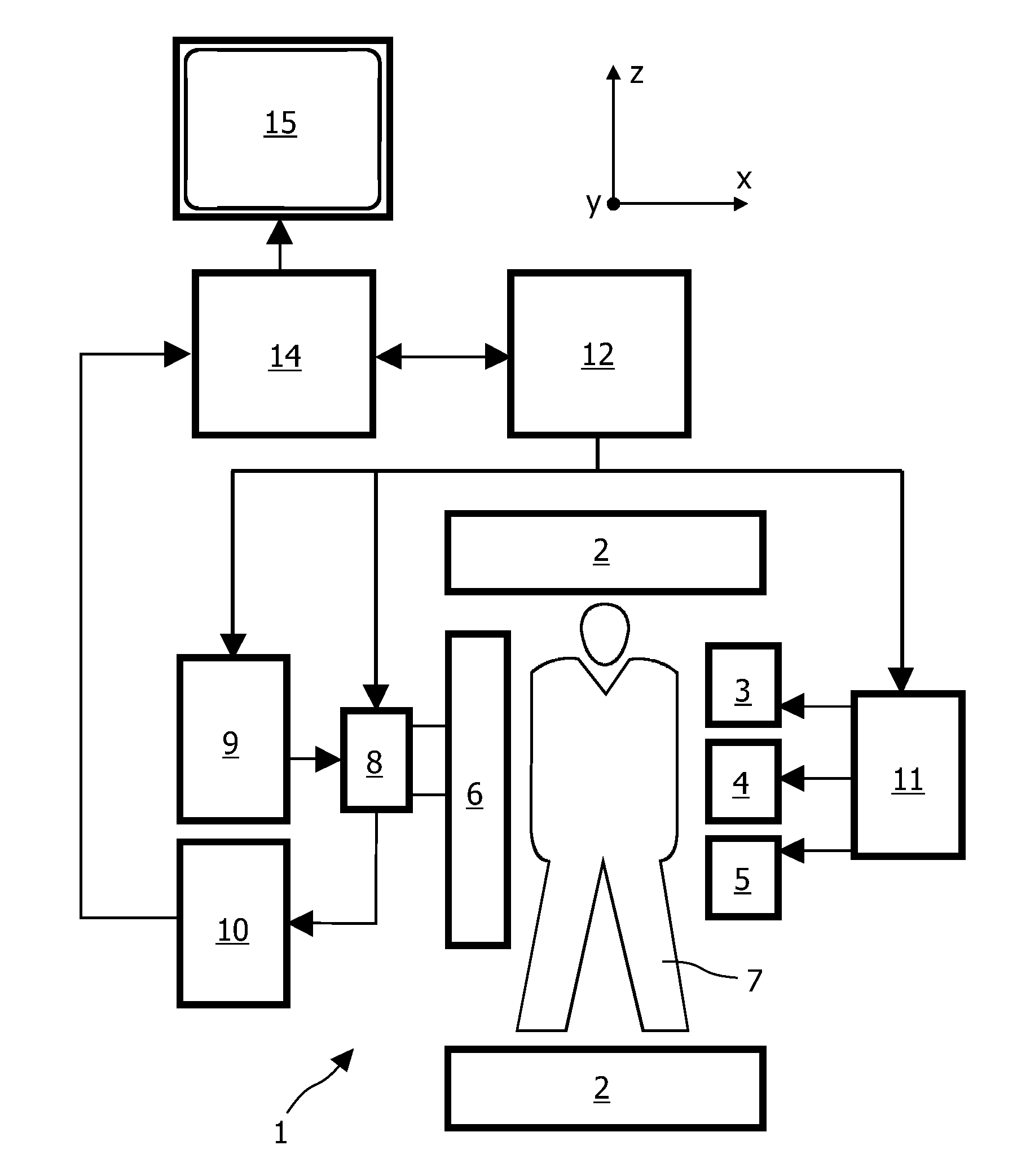
[0030]In FIG. 1 an MRI device 1 in accordance with the present invention is shown as a block diagram. The apparatus 1 comprises a set of main magnetic coils 2 for generating a stationary and homogeneous main magnetic field and three sets of gradient coils 3, 4 and 5 for superimposing additional magnetic fields with controllable strength and having a gradient in a selected direction. Conventionally, the direction of the main magnetic field is labelled the z-direction, the two directions perpendicular thereto the x- and y-directions. The gradient coils 3, 4 and 5 are energized via a power supply 11. The imaging device 1 further comprises an RF transmit antenna 6 for emitting RF pulses to a body 7. The antenna 6 is coupled to a modulator 9 for generating and modulating the RF pulses. Also provided is a receiver for receiving the MR signals, the receiver can be identical to the transmit antenna 6 or be separate. If the transmit antenna 6 and receiver are physically the same antenna as s...


PUM


Abstract

The invention relates to a device for MRI of a body (7) placed in an examination volume. The device (1) comprises means (2) for establishing a substantially homogeneous main magnetic field in the examination volume, means (3, 4, 5) for generating switched magnetic field gradients superimposed upon the main magnetic field, means (6) for radiating RF pulses towards the body (7), control means (12) for controlling the generation of the magnetic field gradients and the RF pulses, means (10) for receiving and sampling MR signals, and reconstruction means (14) for forming MR images from the signal samples. According to the invention, the device (1) is arranged to generate a series of MR signals by subjecting at least a portion of the body (7) to an MRI sequence, to acquire the MR signals as a plurality of k-space blades according to the PROPELLER scheme, to compute phase errors from the phase differences of pairs of k-space blades having different rotation angles, to perform a phase correction of the acquired k-space blades on the basis of the computed phase errors, and to reconstruct an MR image from the acquired and phase-corrected MR data set.

Description

FIELD OF THE INVENTION[0001]The invention relates to a device for magnetic resonance imaging (MRI) of a body placed in an examination volume.[0002]Furthermore, the invention relates to a method for MRI and to a computer program for a magnetic resonance (MR) device.BACKGROUND OF THE INVENTION[0003]In MRI, pulse sequences consisting of radiofrequency (RF) pulses and switched magnetic field gradients are applied to an object (a patient) placed in a homogeneous magnetic field within an examination volume of an MR device. In this way, MR signals are generated, which are scanned by means of RF receiving antennas in order to obtain information about the object and to reconstruct images thereof. Since its initial development, the number of clinically relevant fields of application of MRI has grown enormously. MRI can be applied to almost every part of the body, and it can be used to obtain important functional information about the human body. The pulse sequence, which is applied during an ...

Claims


Application Information

Patent Timeline
Patent Type & Authority Applications(United States)
IPC IPC(8): G01R33/48
CPCG01R33/4824G01R33/561G01R33/5615G01R33/5676G01R33/565G01R33/56509G01R33/5617
Inventor EGGERS, HOGERVAN IJPEREN, GERRIT
Owner KONINKLIJKE PHILIPS ELECTRONICS NV
Why Eureka
Try Eureka