Method and device for normal correction of scanning data in imaging equipment
An imaging device and a technology for scanning data, applied in the field of medical imaging, which can solve problems such as image artifacts and reduce correction data acquisition time.
- Summary
- Abstract
- Description
- Claims
- Application Information
AI Technical Summary
Problems solved by technology
Method used
Image
Examples
Embodiment 1
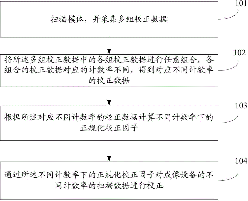
[0096] see figure 1 , which is a flowchart of a method for normalizing and correcting scan data in an imaging device disclosed in Embodiment 1 of the present invention, including the following steps:
[0097]Step 101: scanning the phantom, and collecting multiple sets of calibration data;
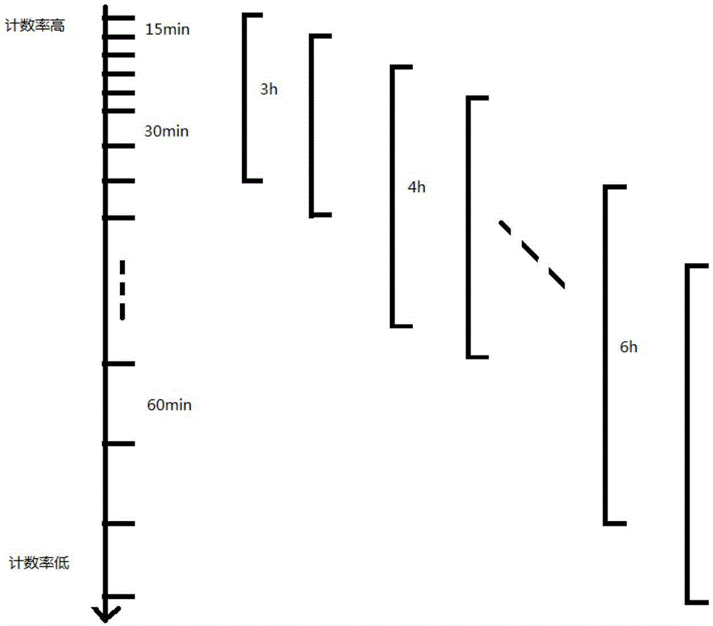
[0098] Use PET or PET / CT and other medical imaging equipment with PET to scan the phantom, and the activity of the scanned phantom can be determined according to the number of groups of collected calibration data. The higher the activity of the phantom, the fewer the number of groups collected, and the lower the activity of the scanned phantom. In addition, the activity of the phantom is also related to the type of scanning. Generally, the activity of the scanned phantom is lower when 3D scanning is used than when 2D scanning is used.
[0099] In the technical solution of the present invention, preferably, in order to obtain more calibration data corresponding to different count rates, ma...
Embodiment 2
[0115] When the technical solution of the present invention uses the CBN method to calculate the normalized correction factors at different count rates, the scanned phantom in Embodiment 1 is a cylindrical phantom, and the collected correction data is the correction data of the cylindrical phantom, corresponding to different count rates. The calibration data is the calibration data of the cylindrical phantom corresponding to different count rates.
[0116] see Figure 5 , which is a flowchart of a method for normalizing and correcting scan data in an imaging device disclosed in Embodiment 2 of the present invention, including the following steps:
[0117] Step 501: scanning the cylindrical phantom, and collecting multiple sets of cylindrical phantom correction data;
[0118] In the CBN method, the formula for calculating the normalization correction factor is: NC uivj =ε ui ε vj b u b v c uimodD c vjmodD d uvrk f uv g uvr , where NC uivj is the normalization correc...
Embodiment 3
[0148] If the CBN method is used to calculate the normalized correction factor at different count rates, the normalized correction factor will also change with time due to the influence of the crystal efficiency factor that changes with time. Therefore, it is necessary to regularly update the normalized correction factor at different count rates. Normalize the correction factor so that the data are regularly corrected using the normalized correction factor at different count rates. The difference between this embodiment and the second embodiment is that it further includes a step of periodically updating the normalization correction factors under different count rates.
[0149] see Figure 7 , which is a flow chart of a method for normalizing and correcting scan data in an imaging device disclosed in Embodiment 3 of the present invention, the method specifically includes:
[0150] Wherein, the following steps 701-705 are applied to the link of calculating the normalization co...
PUM
 Abstract
Description
Claims
Application Information
 - R&D
- Intellectual Property
- Life Sciences
- Materials
- Tech Scout
- Unparalleled Data Quality
- Higher Quality Content
- 60% Fewer Hallucinations
Browse by: Latest US Patents, China's latest patents, Technical Efficacy Thesaurus, Application Domain, Technology Topic, Popular Technical Reports.
© 2025 PatSnap. All rights reserved.Legal|Privacy policy|Modern Slavery Act Transparency Statement|Sitemap|About US| Contact US: help@patsnap.com


