Low cost fundus imager with integrated pupil camera for alignment aid

Pending Publication Date: 2021-12-02
CARL ZIESS MEDITEC INC +1
View PDF0 Cites 0 Cited by
  • Summary
  • Abstract
  • Description
  • Claims
  • Application Information

AI Technical Summary

Benefits of technology

[0019]The above objects are met in a fundus camera optimized to use low cost components, and whose configuration avoids some traditional sources of image artifacts. Additionally, the traditional field-of-view (FOV) is expanded by combining two or more images of different FOVs into a composite image with a larger overall FOV. A first option is to use one or more light emitting diodes (LEDs) as light sources (e.g., miniaturized LEDs and/or high brightness LEDs). These LEDs may be imaged to an eye pupil and located near the camera's imaging stop but laterally offset, which allows the same optics to be used for illumination and detection. This eliminates the need for optics that would traditionally be needed to introduce the light source's optical path to the camera's optical path. Additionally, this positioning of the light sources may be used as part of a pupil splitting design to reduce the amount of reflection artifacts from the eye's o

Problems solved by technology

Nonetheless, it was found that in spite of the use of pupil splitting, reflection artifacts from the cornea (e.g., cornea reflexes) may be enc

Method used


Image

  • Low cost fundus imager with integrated pupil camera for alignment aid
  • Low cost fundus imager with integrated pupil camera for alignment aid
  • Low cost fundus imager with integrated pupil camera for alignment aid

Examples


Example

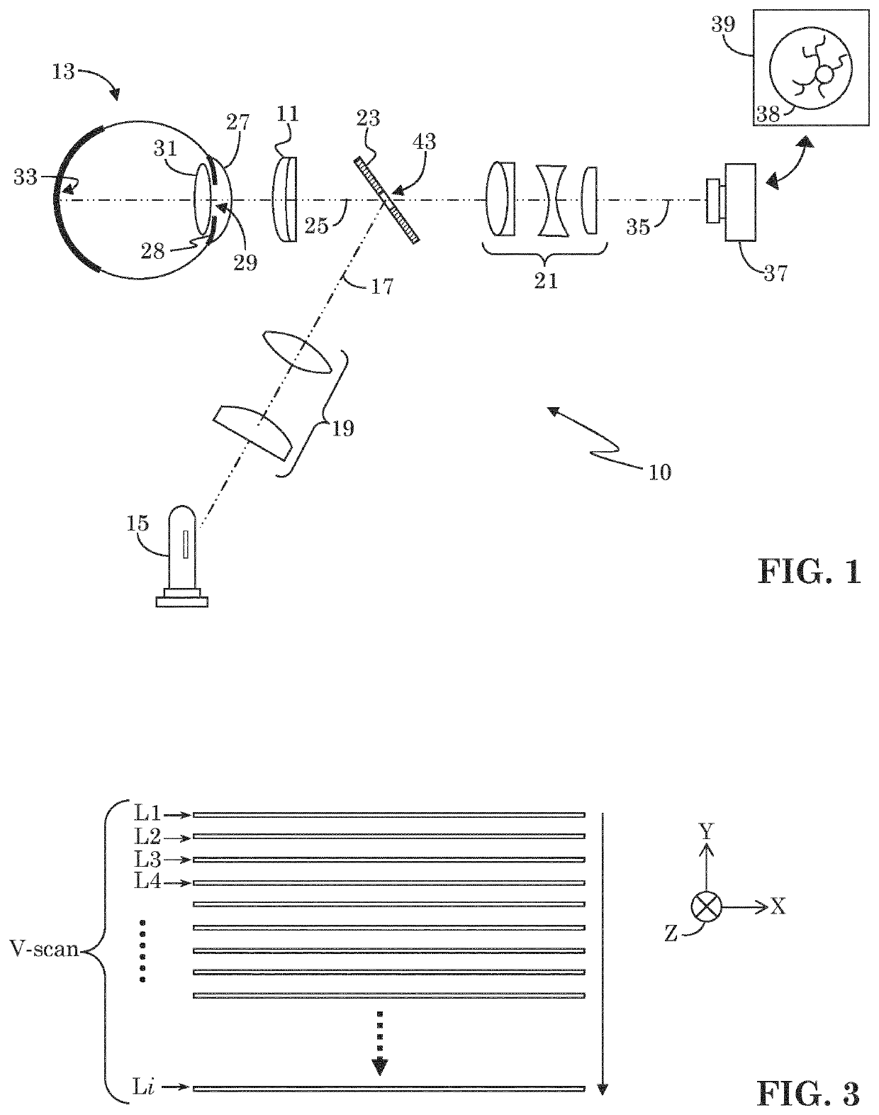
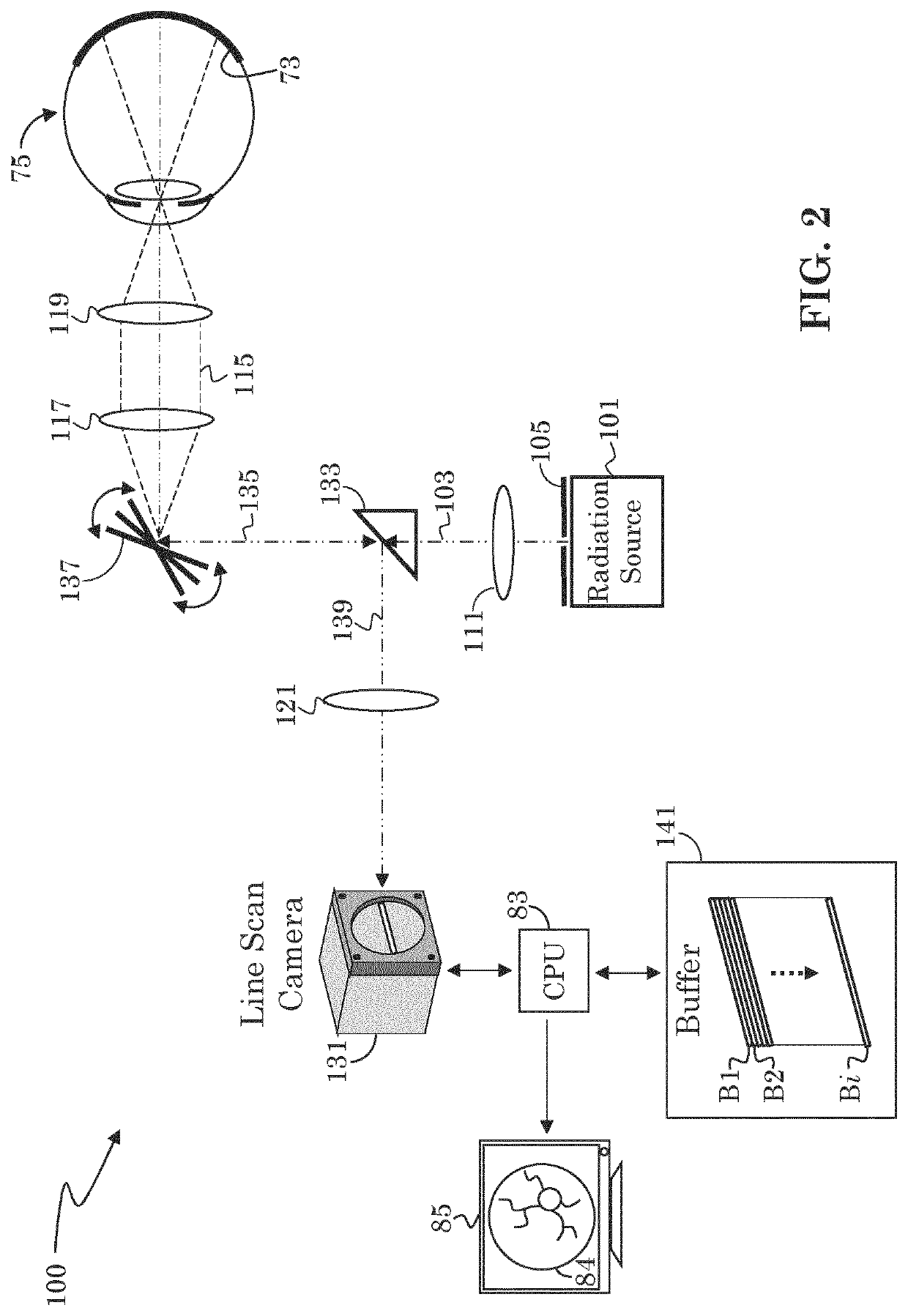
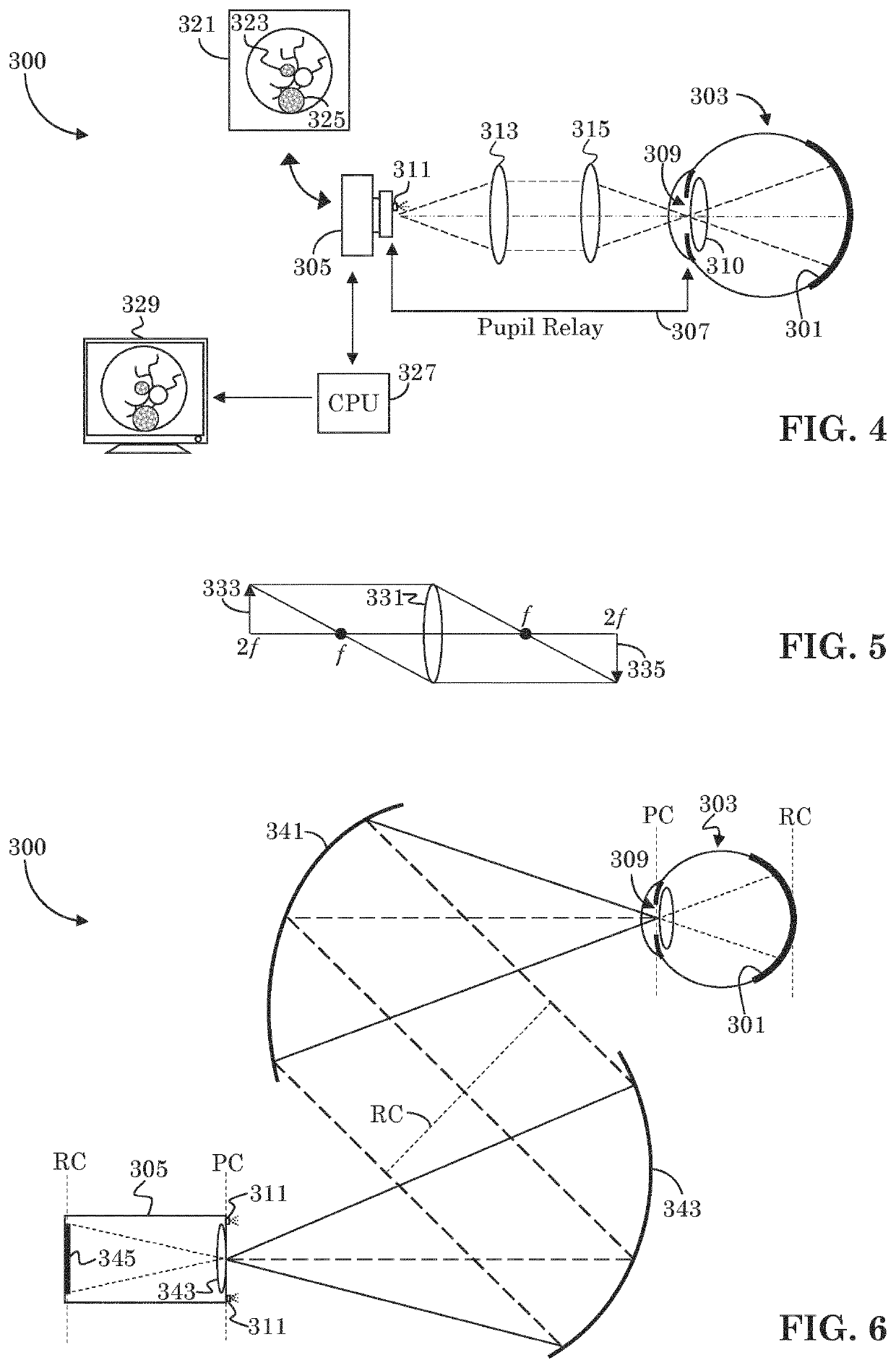
[0047]Fundus imaging is a well-established diagnostic tool in ophthalmology. A fundus camera delivers the illumination light to the back of the eye and collects the light that is reflected back. The primary challenge that any fundus camera has to overcome is to create an artifact-free image by avoiding or eliminating reflections off lenses in the fundus camera and the cornea of the human eye.

[0048]A secondary task of the fundus camera system is to aid in patient alignment or pupil alignment when coupled with another ophthalmic instrument. For example, an optical coherence tomography (OCT) system may include a fundus camera, and may make use of the fundus camera to assure proper alignment of the patient and the OCT system prior to initiating an OCT scanning operation. That is, the fundus camera may provide a real time view of the patient's eye which an OCT operator may use to assure that a desired area of the fundus is in view prior to activating an OCT scanning operation.

[0049]As st...


PUM


Abstract

A low cost fundus camera uses LED light sources placed adjacent the camera's imaging stop, and thereby eliminates the need for optics for introducing the light source to the camera's optical path. Lens reflex in the pupil relay is avoided by using only reflective optics in the pupil relay. Reflex from the LEDs is mitigated by actuating each LED separately, one at a time, and capturing a separate image with each actuated LED. Reflex-free regions of each captured image are extracted and combined to create a composite, reflex-free image.

Description

FIELD OF INVENTION[0001]The present invention is generally directed to the field of fundus imagers. More specifically, it is directed to a low cost fundus imager of improved field of view.BACKGROUND[0002]Various different types of image-capture devices for imaging a sample under test are known. Of particular interest are imaging systems capable of taking close-up images of a specimen with sufficient detail, e.g., sufficient focus, lighting, magnification, and signal-to-noise ratio (SNR). An example of such an imaging system is a fundus imager, which is typically used to image the fundus of an eye. The fundus is the interior surface of the eye opposite the eye lens (or crystalline lens) and may include the retina, optic disc, macula, fovea, and posterior pole. Two categories of imaging systems used to image the fundus are flood illumination imagers and scan imagers. Scan imagers may further be divided into confocal point scanning fundus imagers and line scanning imagers.[0003]Flood i...

Claims


Application Information

Patent Timeline
IPC IPC(8): A61B3/12A61B3/00A61B3/15
CPCA61B3/12A61B3/0033A61B3/158A61B3/0008A61B3/10
Inventor STRAUB, JOCHENSPROWL, ROBERTLIU, YUANEVERETT, MATTHEW J.
Owner CARL ZIESS MEDITEC INC
Why Eureka
Try Eureka