CT system and CT method

a technology of ct system and ct method, applied in the field of ct system and corresponding ct method, can solve the problems of large computation effort, particularly difficult, and impinging on the wrong detector, and achieve the effect of suppressing or eliminating the negative effects of cross-scatter

Active Publication Date: 2020-02-11
KONINKLJIJKE PHILIPS NV
View PDF5 Cites 0 Cited by
  • Summary
  • Abstract
  • Description
  • Claims
  • Application Information

AI Technical Summary

Benefits of technology

[0006]It is an object of the present invention to provide an alternative and improved CT system and CT method with two x-ray sources for suppressing or even completely eliminating the negative effects of cross-scatter.
[0020]The present invention is based on the idea to actively measure the cross-scatter. In particular, the acquisition of data indicative of the amount (and, optionally, spectral footprint) of cross-scattered photons originating from one or more x-ray source(s) other that the one corresponding to the detector is proposed. This additional information is used to seed or fine-tune the correctional measures to avoid imaging artifacts caused by cross-scatter. For this purpose, the fast-switching capability of x-ray sources is exploited to divide the acquisition time into sub-intervals (phases), in which either primary radiation or cross-scatter radiation is measured independently. This, in turn, provides the possibility to gather cross-scatter information on a projection-by-projection basis.
[0022]Hence, according to the present invention the sub-sampling pattern is repetitive within each frame and much more flexible. This makes the sensing of scatter and cross-scatter more homogenous compared to the known solution, i.e. the obtained data including the cross-scatter data is sampled homogenously in time (and hence angle) within each projection interval.
[0023]In a preferred embodiment the read-out units are configured to take the time length of said three different phases into account in the generation of the scatter-corrected read-out signals. This further improves the accuracy of the scatter correction, particularly if the time lengths of the different phases are different.
[0026]In another embodiment each read-out unit comprising a scatter counter and a radiation counter, wherein the control unit is configured to control the read-out units such that radiation detected by a detector during a phase in which the corresponding x-ray source is switched off is read out by the scatter counter of the corresponding read-out unit to obtain a scatter signal and that radiation detected by the same detector during a phase in which the corresponding x-ray source is switched on is read out by the radiation counter of the same read-out unit to obtain a radiation signal, and wherein the read-out units are further configured to correct scatter by subtracting the scatter signal from the radiation signal read out by the scatter counter and the radiation counter of the same read-out unit to obtain the scatter-corrected read-out signals. This provides a simple and reliable implementation. Preferably, in this embodiment the ratio of the respective sampling durations in the various phases, i.e. the time length of said three different phases, is taken into account in the generation of the scatter-corrected read-out signals.

Problems solved by technology

This is particularly difficult in dual source systems, where sources influence each other's corresponding detectors with cross-scatter, i.e. photons from one source may impinge on the wrong detector due to scattering through the patient or object.
Further, such anti-scatter corrections to some extent require a large degree of computation effort.

Method used


Image

  • CT system and CT method
  • CT system and CT method
  • CT system and CT method

Examples


first embodiment

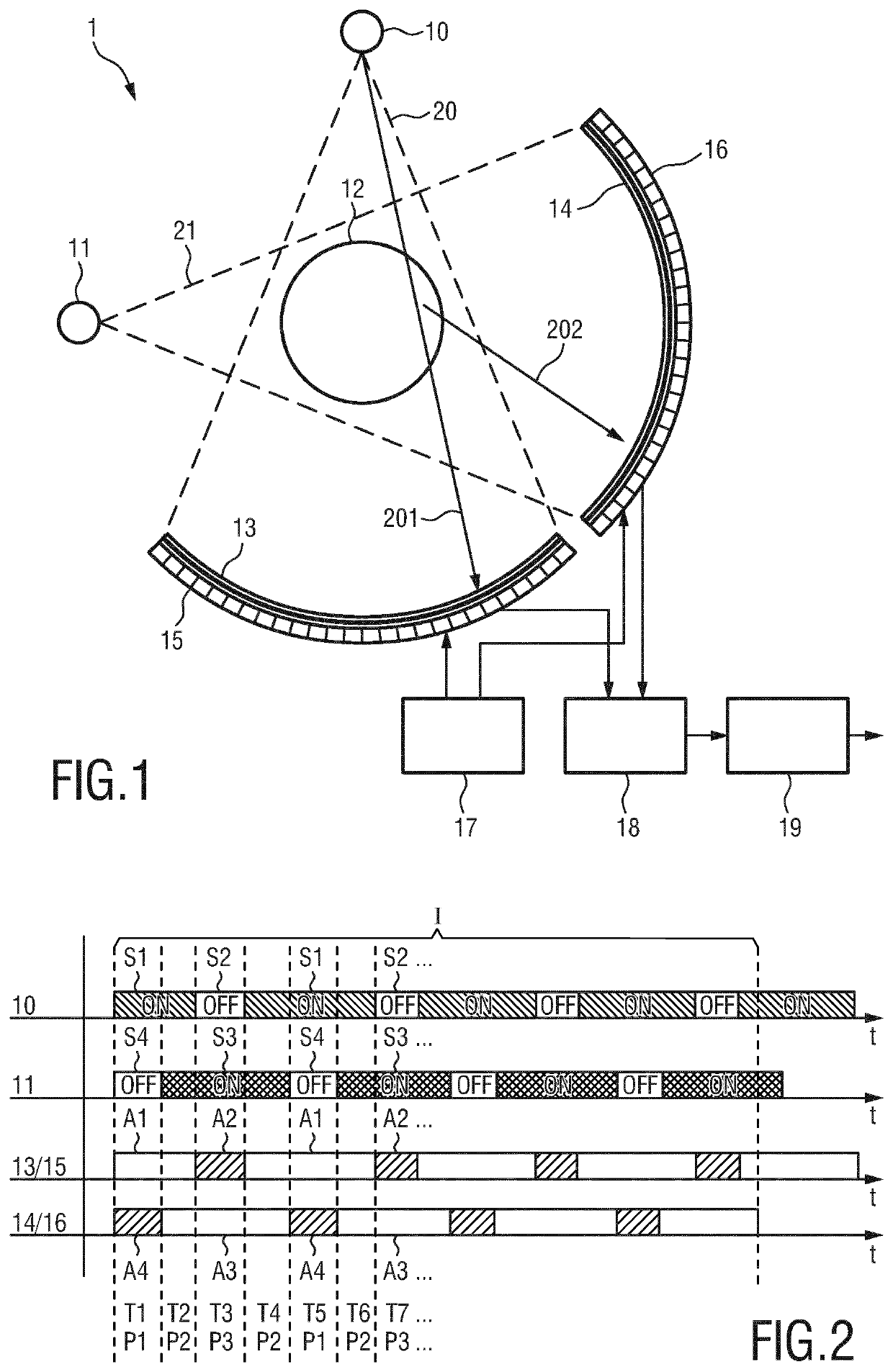
[0045]FIG. 1 shows a schematic diagram of a CT system 1 according to the present invention. It comprises two x-ray sources 10, 11, which are in this example displaced by a rotational angle of about 90°, for rotating about and concurrently or subsequently emitting radiation 20, 21 through an imaging region 12, in which an object of examination is arranged, e.g. a patient on a patient table. Two detectors 13, 14, one per x-ray source 10, 11, are arranged opposite the respective x-ray source 10, 11, for detecting radiation after penetration through the imaging region 12. Two read-out units 15, 16, one per detector 13, 14, are provided for reading out (preferably per pixel or groups of pixels) the detected radiation from the respective detector 13, 14. Further, a control unit 17 is provided for controlling said x-ray sources 10, 11 and said read-out units 15, 16. An optional scatter correction unit 18 generates scatter-corrected read-out signals from the detected radiation. Alternativel...

second embodiment

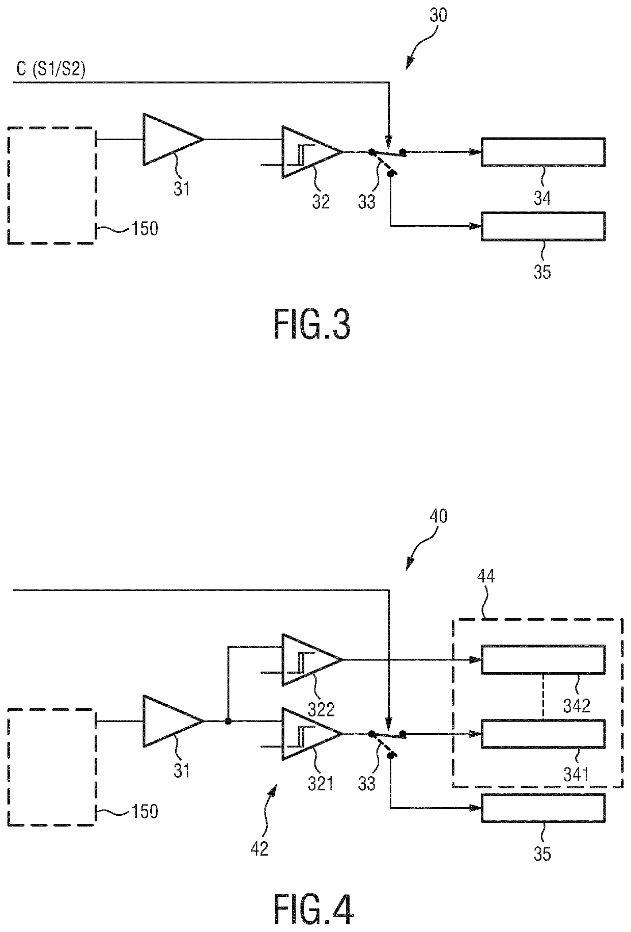
[0066]In the embodiment shown in FIG. 3 it was assumed that only one threshold is available. FIG. 4 shows a circuit diagram of a read-out unit 40 according to the present invention applying a multi-bin topology. In this embodiment, the single radiation counter 34 is replaced by a multi-bin radiation counting unit 44 comprising multiple counters 341, 342, and the single discriminator 32 is replaced by a multi-bin discriminator unit 42 comprising multiple discriminators 321, 322 (applying different thresholds) coupled to the respective counter 341, 342 to obtain spectral information for the detected radiation.

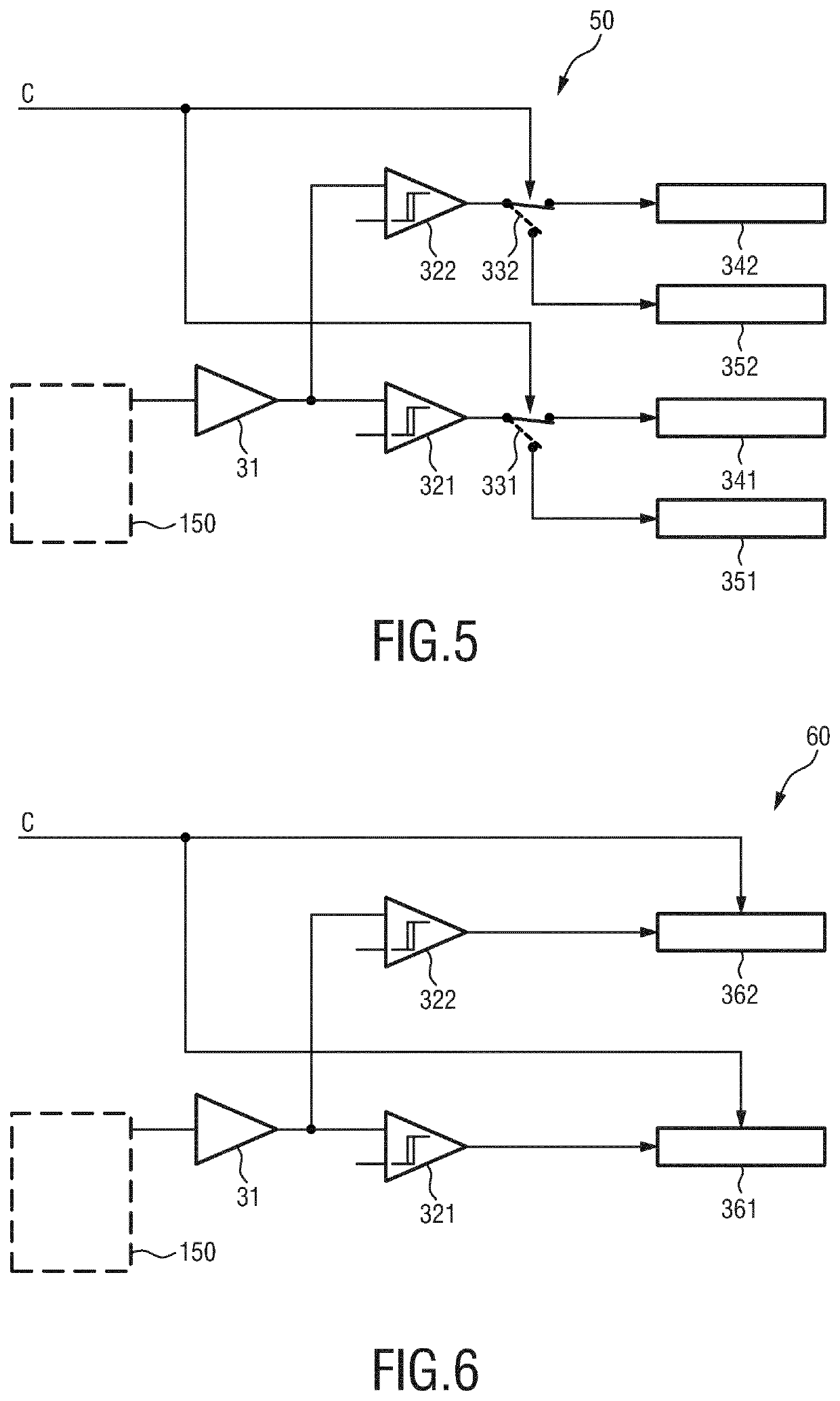
[0067]In the read-out unit 40 a single scatter counter 35 at the lowest threshold is used, considering in this case that the energy information of the scatter photons is not of primary interest. In an alternative embodiment of a read-out unit 50 shown in FIG. 5 the same degree of spectral differentiation is provided for both primary and scattered photons. For this purpose the sin...

fifth embodiment

[0076]FIG. 8 shows a circuit diagram of a read-out unit 70 according to the present invention for implementing the embodiment illustrated in FIG. 7. Based on the status of the sources 10, 11 three different enabling (control) signals E1, E2 and E3 are generated by an enabling logic 38 for enabling a respective counter 371, 372, 373. For read-out unit 15 the counter 371 is enabled during acquisition mode B3 (phase P3), the counter 372 is enabled during acquisition mode B1 (phase P1), and the counter 373 is enabled during acquisition mode B2 (phase P2). As for earlier embodiments, the radiation counters 371 and 372 are expected to be significantly smaller than the counter 373.


PUM

PropertyMeasurementUnit
rotational angleaaaaaaaaaa
switching timeaaaaaaaaaa

Abstract

The present invention relates to a dual- or multi-source CT system and method. For suppressing or even completely eliminating the negative effects of cross-scatter, the proposed CT system comprises two x-ray sources (10, 11), two detectors (13, 14), two read-out units (15, 16), a control unit (17) and a reconstruction unit (19). Further, a scatter correction unit (18) is provided or the read-out units (15, 16) are configured to generate scatter-corrected read-out signals from the detected radiation, wherein a scatter-corrected read-out signal is generated from the radiation detected by a detector during a single projection interval (I) including multiple repetitions of three phases, in which the sources are alternately switched on and off and in which the read-out units alternately register primary radiation or cross-scatter radiation.

Description

CROSS REFERENCE TO RELATED APPLICATIONS[0001]This application is the U.S. National Phase application under 35 U.S.C. § 371 of International Application No. PCT / EP2016 / 074443, filed Oct. 12, 2016, published as WO 2017 / 071952 on May 4, 2017, which claims the benefit of European Patent Application Number 15191824.0 filed Oct. 28, 2015. These applications are hereby incorporated by reference herein.FIELD OF THE INVENTION[0002]The present invention relates to a CT system and a corresponding CT method.BACKGROUND OF THE INVENTION[0003]In Computed Tomography (CT) measures are in place to avoid that scatter photons impinge on the detector. To this end, so called anti-scatter grids have evolved to offer scatter attenuation on both angular (phi) and longitudinal (z) directions. However, despite such measures, sophisticated Monte Carlo based software corrections are required in order to completely eliminate the remaining artifacts caused by scatter events. This is particularly difficult in dual...

Claims


Application Information

Patent Timeline
Patent Type & Authority Patents(United States)
IPC IPC(8): G01N23/04A61B6/00A61B6/03G01N23/046
CPCG01N23/046A61B6/4014A61B6/032A61B6/5282G01T1/2985
Inventor STEADMAN BOOKER, ROGERROESSL, EWALD
Owner KONINKLJIJKE PHILIPS NV
Why Eureka
Try Eureka