Active antenna system and methods of testing

a technology of active antennas and antennas, applied in the direction of antennas, receiver monitoring, antenna details, etc., can solve the problems of high degree of measurement uncertainty, inability to represent performance, and compromise the future functionality of aas

Active Publication Date: 2016-09-01
ANALOG DEVICES INT UNLTD
View PDF2 Cites 48 Cited by
  • Summary
  • Abstract
  • Description
  • Claims
  • Application Information

AI Technical Summary

Benefits of technology

[0033]In one optional example, the method may further comprise scaling a conductively coupled test signal to negate an effect on a test result of a transfer function of a signal routed between the externally connectable RF test port and a respective antenna port of the active antenna system.

Problems solved by technology

Testing units in a disassembled or partially disassembled state inherently affects electromagnetic radiation patterns for antenna measurements and, thus, leads to results that would therefore not be representative of the performance expected if the AAS were fully assembled in a field-deployed system.
Further, any form of disassembly requires breaking environmental and security seals, which would compromise the future functionality of the AAS.
Multipath signals would distort, for example, the signal received in a probe antenna measuring an AAS in an anechoic chamber causing a high degree of measurement uncertainty or distorting the results to an indeterminate level.
Therefore, very large anechoic chambers would be required.
The near field probe itself adds a huge degree of uncertainty to the test results and the performance of the probe directly impacts the test results.
Further, the near field probe is not suitable for many measurements, such as error vector magnitude (EVM), as the near field combination of signals from multiple sources can distort the signal detected by the probe.
Therefore, there can be significant differences between near field, far field and conducted measurements.

Method used


Image

  • Active antenna system and methods of testing
  • Active antenna system and methods of testing
  • Active antenna system and methods of testing

Examples


Embodiment Construction

[0049]Example embodiments of the invention are described with reference to smart (or active) antenna technology used in a wireless communication system.

[0050]The following description focuses on embodiments of the invention that are applicable to active antenna arrays employed in Universal Mobile Telecommunication System (UMTS) cellular communication systems and in particular to a UMTS Terrestrial Radio Access Network (UTRAN) operating in a 3rd generation partnership project (3GPP™) system, and evolutions to this standard such as HSPA+ or long term evolution (LTE) system. However, it will be appreciated that the invention is not limited to this particular cellular communication system, but may be applied to any wireless communication system, including satellite communication systems, employing antenna arrangements.

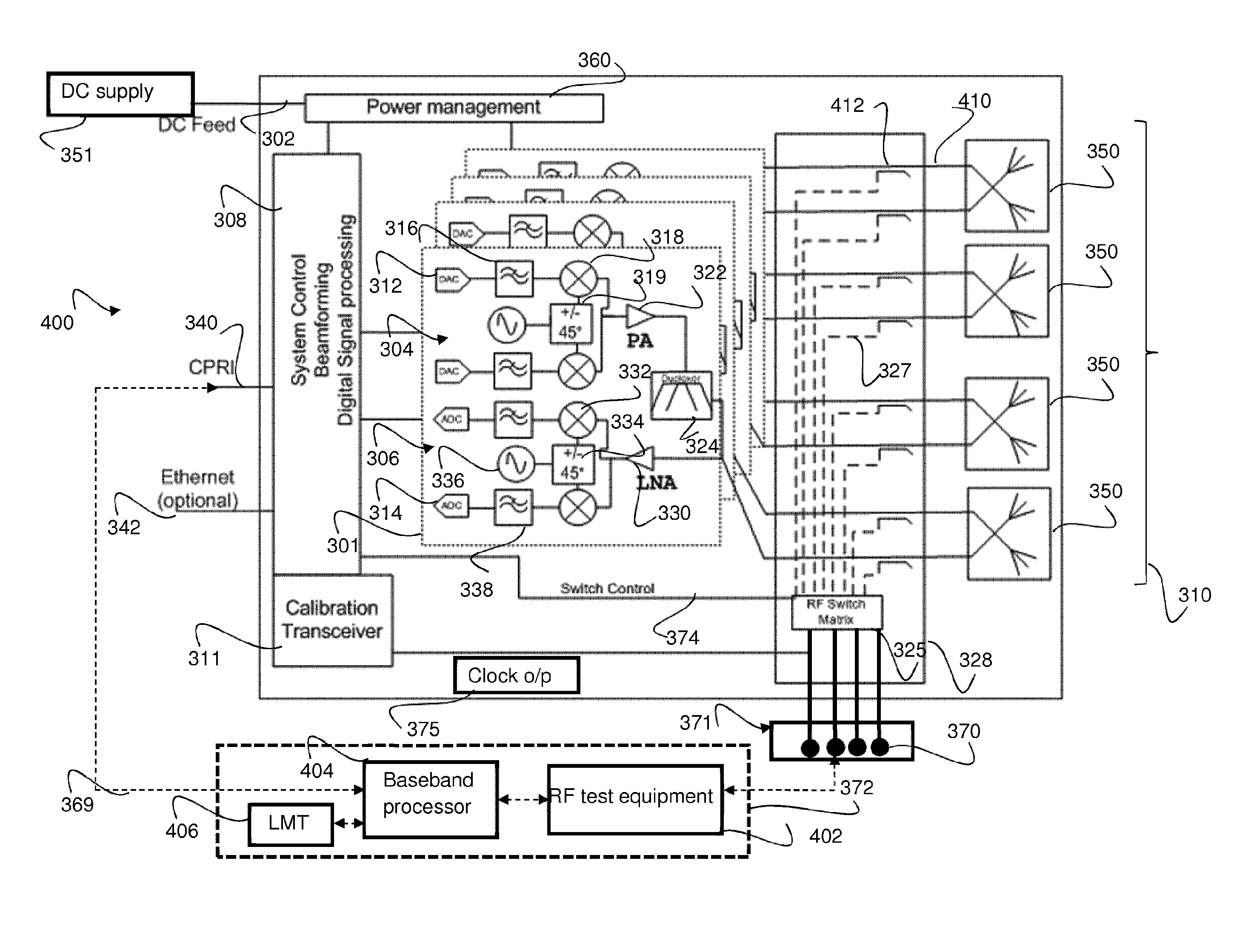
[0051]Referring to FIG. 3, an example of an AAS 300 adapted to support example embodiments of the invention is illustrated. The example AAS 300 comprises a CPRI interface ...


PUM


Abstract

An active antenna test system is described. The active antenna test system comprises an active antenna unit comprising: a plurality of antenna elements; at least one processor; a plurality of transceiver modules operably coupled to the at least one processor and arranged to receive at least one first baseband signal for transmission via at least one of the plurality of antenna elements and arranged to pass at least one second baseband signal thereto received and down-converted from at least one of the plurality of antenna elements; and at least one switching module operably coupling the plurality of antenna modules to the plurality of transceiver modules. The active antenna test system also comprises at least one communication test equipment, such as a radio frequency, RF, test module and at least one baseband processor. The active antenna unit further comprises at least one externally connectable radio frequency, RF, test port operably coupled to the at least one switching module and arranged to externally couple the at least one communication test equipment to at least one of the plurality of transceiver modules for conductive testing.

Description

FIELD OF THE INVENTION[0001]The field of the invention relates to an antenna arrangement and methods of testing, and in particular methods of testing applicable to Active Antenna Systems.BACKGROUND OF THE INVENTION[0002]In traditional radio networks comprising of basestation(s) and passive antenna systems, there is at least one connectorised 50Ω port on the antenna and at least one connectorised 50Ω port on the basestation that allows signals to be passed there between via at least one 50Ω connectorised cable. The connectors on the base station could be, for example, 7 / 16 DIN RF connectors or N-type RF connectors. The connectorised 50Ω base station and antenna port(s) can also be used as one or more test port(s), to facilitate test and power calibration of radio frequency (RF) transceiver circuit(s) of the basestation. Advantageously, connectorised 50Ω port(s) used to allow interconnect to antenna can instead be coupled to test equipment to allow measurements to be performed on the ...

Claims


Application Information

Patent Timeline
Patent Type & Authority Applications(United States)
IPC IPC(8): H04B17/19H04B17/14H01Q21/24H01Q1/24
CPCH04B17/19H01Q21/24H04B17/14H01Q1/246H01Q3/267H04B17/21
Inventor O'KEEFFE, CONORNORMANTON, ADRIAN
Owner ANALOG DEVICES INT UNLTD
Why Eureka
Try Eureka