Thermal package wth heat slug for die stacks

a technology of heat slugs and die stacks, which is applied in the direction of semiconductor devices, semiconductor/solid-state device details, electrical devices, etc., can solve the problems of increasing processor speeds, reducing the surface area available for dissipating heat, and reducing the size of dies in general, so as to improve and facilitate manufacturing. , the effect of improving the heat dissipation and thermal connection

Inactive Publication Date: 2013-10-24
SONY MOBILE COMM INC +1
View PDF1 Cites 47 Cited by
  • Summary
  • Abstract
  • Description
  • Claims
  • Application Information

AI Technical Summary

Benefits of technology

[0024]According to another aspect of the invention, the top most die in the die stack has its exposed ends of its TSV:s in thermal contact with the heat spreader. The effect of this is that it is the last or outmost die in the stack that has its TSV:s in thermal contact with the heat spreader improving heat dissipation and thermal connection to the heat spreader.
[0025]According to yet another aspect of the invention, each TMV is linearly aligned with a corresponding conduct connected via solder joints to the PWB. The TMV:s:s are linearly aligned because it makes the semiconductor package easier to manufacture, e.g. when placing the dies on each other and when soldering the connections between the dies but also between the dies and the PWB. So from a structural design point of view it is easier to manufacture the device if the TSV:s, the TMV:s, the conducts and the solder balls are linearly aligned. Moreover, with TMV:s placed in direct alignment with thermal conducts / connections and / or connectors, in package substrate and solder joints to PWB, an optimal dissipating heat transfer away from heat spreader and package to the PWB, is obtained.
[0026]In some embodiments / aspects, the TSV:s extend from the “hot spots” of the package to the heat spreader and joins the heat spreader by means of a transition section forming a thermal connection at each TSV end and the heat spreader forms a heat buffer and heat conductor thermally connected at its outer perimeter to through-mold-vias (TMV:s) extending down to the PWB through stacked vias in package substrate, which act as thermal connectors in the substrate, to / via corner solder balls from the package to the PWB and through thermal conducts / connectors (i.e. stacked vias) in the PWB into the ground layer of the PWB (may be ground layers in the centre of the PWB) for lateral heat spread. Similarly, the ability to withstand an increased heat generation is improved further, since the TSV:s, TMV:s, heat spreader and thermal conducts and connectors “smears out” the excessive heat faster and increases the volume / thickness of the heat flow paths in the package and the PWB between the heat generating active portions of the dies and the ground layer of the PWB such that the negative impacts of the excessive heat is reduced due to both a faster heat flow / dissipation response time and transient heat peaks, also reducing negative impacts of excessive heat in sustainable situations.

Problems solved by technology

However, upper or outer vertical dies impede dissipation of heat from lower or inner dies or other components and prevalently increasing processor speeds may generate more heat than previous processors.
At the same time, the sizes of dies in general have been reduced, which reduces the surface area available for dissipating heat.

Method used


Image

  • Thermal package wth heat slug for die stacks
  • Thermal package wth heat slug for die stacks
  • Thermal package wth heat slug for die stacks

Examples


first embodiment

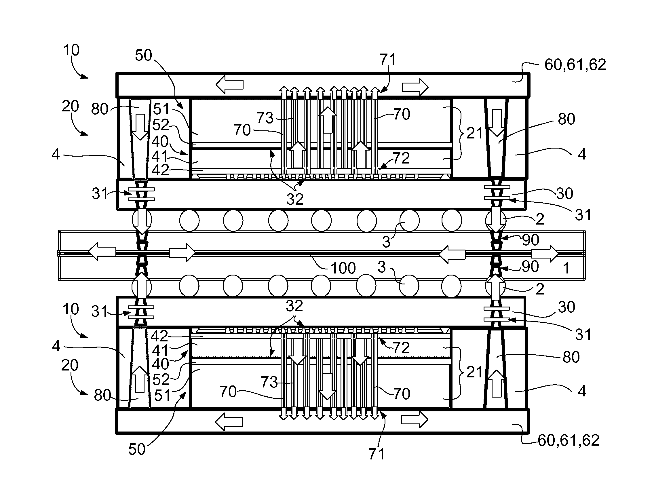
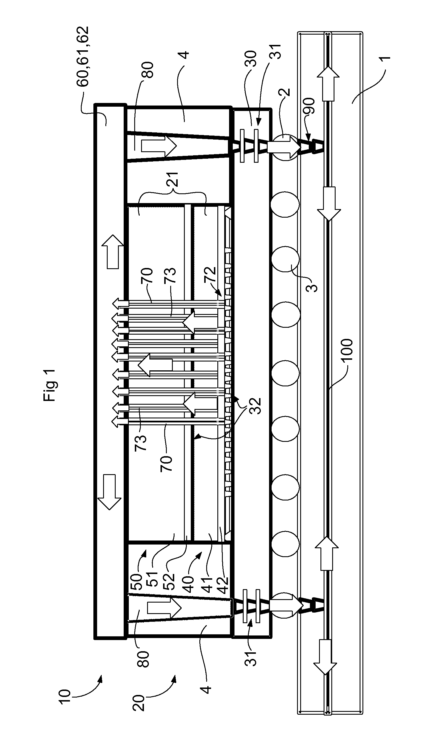
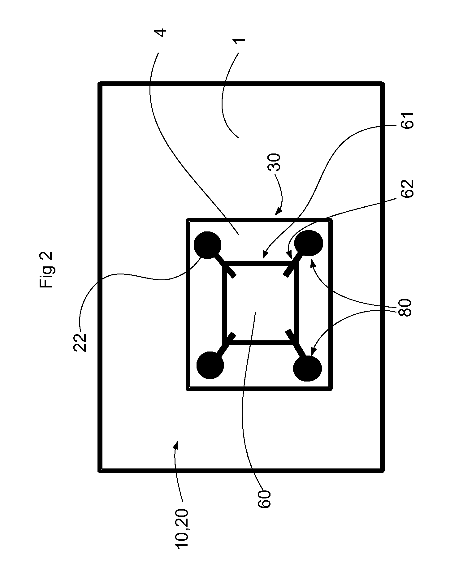
[0033]A semiconductor assembly 10 according to the invention is shown in FIGS. 1 to 4, wherein like reference numerals designate corresponding or similar elements throughout the views, a semiconductor assembly 10 is shown in FIG. 1. A package 20 comprising a die stack 21 is included in the semiconductor assembly 10 and may have a die-die connection using a Micro Pillar Grid Array (MPGA) in the package. The die stack 21 comprising dies 40, 50, the package 20 and a printed circuit / wiring board 1 are operatively connected in a known way by solder joints 2, which connections will not be explained in detail as the skilled person is aware of this technique.

[0034]The die stack 21 includes a first die / an lower die 40, at least one further / second / upper die 50, and a package substrate 30. The dies disclosed herein are semiconductors that may have passive portions 41, 51, active portions 42, 52 or any combination or number of such portions depending on the desired function and application of t...

second embodiment

[0043]The dies 40, 50 of the semiconductor assembly 10 and the others described herein may be made based on silicon (Si) and variants thereof. In some cases for example germanium (Ge) or Ge and carbon are added to Si to increase charge carrier mobility. Alternative materials may include but not be limited to gallium arsenide (GaAs), indium phosphide (InP), graphene, or other III-IV semiconductor compounds. Further, although Through-Silicon Vias are referred to herein as TSV:s because of the prevalence of the use of silicon, in light of the fact that other materials may be used for the die, the term TSV is understood to apply to a like passage regardless of the die material In the embodiment shown in FIGS. 1-4, the upper die 50 may be, for example, a DRAM, and the lower die 40 may be a CPU die. However, various components may be used in such an arrangement, including but not limited to stacking of processor blocks. In a semiconductor assembly 10 shown in FIG. 4, a package 200 include...


PUM


Abstract

A semiconductor assembly comprises a package, which in turn comprises at least one substrate, a first die stacked onto the substrate, at least one further die stacked onto the first die, at least one heat spreader in the package, and TSV:s extending through the stacked dies. The ends of the TSV:s are exposed at the further die.

Description

TECHNICAL FIELD OF THE INVENTION[0001]The present invention relates to integrated circuits and associated electronics, and particularly to heat dissipation features of vertically stacked dies in packages and other printed board assemblies.BACKGROUND ART[0002]In three dimensional packaging, connected integrated circuits are made more compact by vertically stacking two or more dies with a high speed and substantially direct interface. The main reason for vertically stacking dies is better signal performance, i.e. stacked dies are less parasitic as wire length is reduced. Micro ball connections that may be used with vertical die stacks instead of relatively long leads on the periphery of the chips may reduce elapsed time for communication of signals between components, thus increasing speed as wire lengths both between dies in a system and between the circuit and the circuit board may be shortened. In the case of CPU and dynamic random access memory (DRAM) dies, this effect is manifest...

Claims


Application Information

Patent Timeline
Patent Type & Authority Applications(United States)
IPC IPC(8): H01L23/34
CPCH01L23/34H01L2224/16225H01L2224/32225H01L2224/73204H01L2924/15311H01L23/36H01L23/3677H01L23/3735H01L23/4334H01L25/0657H01L2225/06517H01L2225/06589H01L2225/06513H01L2225/06541H01L2225/06565H01L2924/00
Inventor LUNDBERG, NILS
Owner SONY MOBILE COMM INC
Why Eureka
Try Eureka