Method and apparatus for meniscal repair

a meniscus and surgical technology, applied in the field of surgical methods and equipment, can solve the problems of frequent damage to the meniscus b>5/b>, affecting the proper motion of the knee joint, and patients having a partial or complete removal of the meniscus, etc., and achieves the effect of convenient, safe and reliabl

Inactive Publication Date: 2010-05-13
ENTERPRISES HLDG INC
View PDF76 Cites 16 Cited by
  • Summary
  • Abstract
  • Description
  • Claims
  • Application Information

AI Technical Summary

Benefits of technology

[0010]The present invention provides an improved method and apparatus for meniscal repair which addresses the problems associated with the prior art. More particularly, the present invention comprises the provision and use of a novel meniscal suturing system which makes suturing of the meniscus easy, safe and reliable.

Problems solved by technology

Meniscus 5 is frequently damaged (e.g., torn) as the result of injury and / or accident.
A damaged meniscus can impede proper motion of the knee joint and cause pain, among other things.
However, it was subsequently recognized that patients having a partial or complete removal of their meniscus frequently suffered from long term joint problems, e.g., arthritis.
Suturing a tear in the meniscus has heretofore been technically difficult.
This is because the knee joint is a relatively tight space and has limited access points, thus making it hard to maneuver suturing instruments and visualization devices.
In addition, there are delicate blood vessels and nerves adjacent to the knee joint (e.g., at the back of the knee) which can be easily damaged, particularly by the sharp needles used to place the suture.
However, all of the fasteners developed to date tend to suffer from one or more disadvantages.
Among these is the common—and quite significant—disadvantage associated with positioning a rigid component within the interior of the knee.
If the rigid component is not properly positioned at the time of deployment, and / or if the rigid component should subsequently migrate out of position, serious joint abrasion can result.

Method used


Image

  • Method and apparatus for meniscal repair
  • Method and apparatus for meniscal repair
  • Method and apparatus for meniscal repair

Examples


Embodiment Construction

First Preferred Method and Apparatus

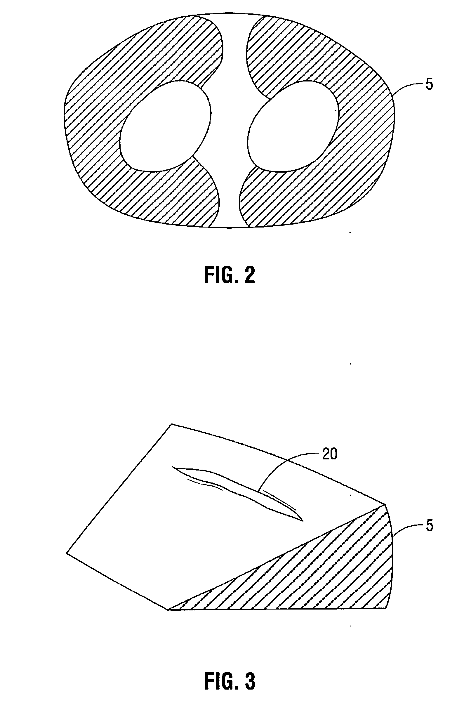
[0042]Looking first at FIGS. 4 and 5, there is shown an apparatus 100 for use in closing tear 20 in meniscus 5.

[0043]More particularly, in one preferred form of the present invention, and still looking now at FIGS. 4 and 5, a first needle 105 is first advanced so that its distal tip 110 is positioned within, but not completely through, meniscus 5.

[0044]Next, as seen in FIG. 6, a second needle 115 is advanced completely through the meniscus, so that the distal tip 120 of second needle 115 is positioned on the far side of the meniscus.

[0045]Then, and looking now at FIGS. 7-9, a snare 125 is advanced out the distal end 120 of second needle 115. Snare 125 is formed and arranged so that when the snare is in its fully-extended position (FIG. 9), the loop 130 of snare 125 is axially aligned with the longitudinal axis 135 of first needle 105. To this end, snare 125 may comprise an elongated body 140 having the loop 130 set at its distal end, with loop 130...


PUM


Abstract

An apparatus for suturing tissue includes a housing. The apparatus also includes a first needle attached to the housing and a second needle attached to the housing. A suture having a leading portion and a trailing portion is also included. A first structure is operably associated with the first needle for passing the leading portion of the suture from a near side of body tissue to a far side of the body tissue. A second structure is operably associated with the second needle for retracting the leading portion of the suture from the far side of the body tissue back to the near side of the body tissue.

Description

REFERENCE TO PENDING PRIOR PATENT APPLICATIONS [0001]This patent application claims priority to, and the benefit of, co-pending U.S. patent application Ser. No. 11 / 805,223, filed on May 22, 2007, which claims priority to U.S. Provisional Patent Application Ser. No. 60 / 802,378, filed on May 22, 2006 and U.S. Provisional Patent Application Ser. No. 60 / 921,403, filed on Apr. 2, 2007. The above-identified prior applications are hereby incorporated by reference in their entireties.FIELD OF THE INVENTION[0002]This invention relates to surgical methods and apparatus in general, and more particularly to surgical methods and apparatus for the repair of the meniscus.BACKGROUND OF THE INVENTION[0003]Looking first at FIGS. 1 and 2, the meniscus 5 is a piece of cartilage located in the knee joint, between the top of the tibia 10 and the bottom of the femur 15. Meniscus 5 serves to facilitate stable movement of the tibia and femur relative to one another, and to absorb shock and to spread load.[0...

Claims


Application Information

Patent Timeline
Patent Type & Authority Applications(United States)
IPC IPC(8): A61B17/04
CPCA61B17/0469A61B17/0485A61B2017/0646A61B2017/0474A61B17/06061A61B2017/06052A61B2017/0475A61B2017/0496A61B2017/0472A61B2017/0477
Inventor MARSHALL, PETERHUBBARD, DENNIS
Owner ENTERPRISES HLDG INC
Why Eureka
Try Eureka