Extraction device for extracting a trim weight from a rotor blade

a technology for extracting devices and rotor blades, which is applied in the direction of rotorcraft, transportation and packaging, aircrafts, etc., can solve the problems of inability to extract time-consuming and cost-intensive extraction, and devices that are not suitable for extracting trim weights from rotor blades. , to achieve the effect of convenient, safe and reliable method

Inactive Publication Date: 2017-10-26
AIRBUS HELICOPTERS DEUT GMBH
View PDF16 Cites 5 Cited by
  • Summary
  • Abstract
  • Description
  • Claims
  • Application Information

AI Technical Summary

Benefits of technology

[0014]Therefore, an object of the present invention consists in providing an extraction device for extracting a trim weight from a rotor blade, which enables an access to the relatively difficult to access trim weights through access openings provided in the rotor blades in an easy, safe, and reliable manner. Moreover, it is an object of the present invention to provide a method for using such an extraction device.
[0019]Since the threaded rod is preferably at least partly plastically deformable, it can be deformed plastically prior to being used correspondingly for extracting the trim weight from the rotor blade, so as to enable an easy and uncomplicated access to the trim weight in the rotor blade. In particular, an alignment of the threaded rod resp. the spreading arms in relation to the opening of the trim weight can thereby be achieved.
[0020]Advantageously, the extraction device according to the invention enables comparatively high tensile loads of up to 200 N during extraction in case of openings in corresponding trim weights with a maximum diameter of 3.5 mm. Moreover, the threaded rod, which is at least partly plastically deformable, does not only enable an alignment of the spreading arms in relation to the respective opening of a trim weight, but also an access to trim weights which are very difficult to access. Accordingly, trim weights which cannot be extracted using conventional hand tools, can now be extracted easily. This advantageously reduces the period of time and the costs of corresponding maintenance works. Moreover, the extraction device according to the invention is comparatively cost-efficient and easy to handle so that no time-consuming trainings resp. briefings are required.
[0030]According to another preferred embodiment, the at least one elastic pretensioning element is adapted for preventing slipping out of the at least one spreading wedge from an accommodation area provided between the at least two elastically deformable spreading arms.

Problems solved by technology

However, the trim weights in the trim weight boxes or housings, resp. in the associated rotor blades, are in general relatively difficult to access.
In general, a required extracting of trim weights from rotor blades is effected manually using customary hand tools, since a tool dedicated to such an extracting has not yet been available so that such a required removing resp. extracting is generally time-consuming and, thus, cost-intensive.
However, these devices are not suitable for extracting trim weights from rotor blades, as described hereinafter.
However, the handling of all devices described above is comparatively complicated resulting in their use being time-consuming.
Moreover, these devices cannot be used for extracting trim weights from rotor blades, since due to the rigid structure of the respective individual components, in particular of the transmission rod and the screwing spindle resp. the thread element and the outer sleeve as such, a respective access to the relatively difficult to access trim weights through the access openings provided in the rotor blades is not possible.
For this purpose, however, the threaded rod and the tension screw must first be arranged on opposing axial ends of the bearing bush, so that the extraction device can only be used for continuous openings resp. through holes.
Accordingly, this extraction device cannot be used with blind holes.
Moreover, this extraction device cannot be used for extracting trim weights from rotor blades, since due to the rigid structure of its individual components, in particular of the threaded rod and the tension screw, access to the relatively difficult to access trim weights through the access openings provided in the rotor blades is not possible.

Method used


Image

  • Extraction device for extracting a trim weight from a rotor blade
  • Extraction device for extracting a trim weight from a rotor blade
  • Extraction device for extracting a trim weight from a rotor blade

Examples


Embodiment Construction

[0045]In the following description, the terms left, right, front, rear, top, and bottom refer to the respective figure and may vary from one figure to another depending on the selected orientation (portrait or landscape format). Equal or equally acting parts are given the same reference in different figures and are usually described only once.

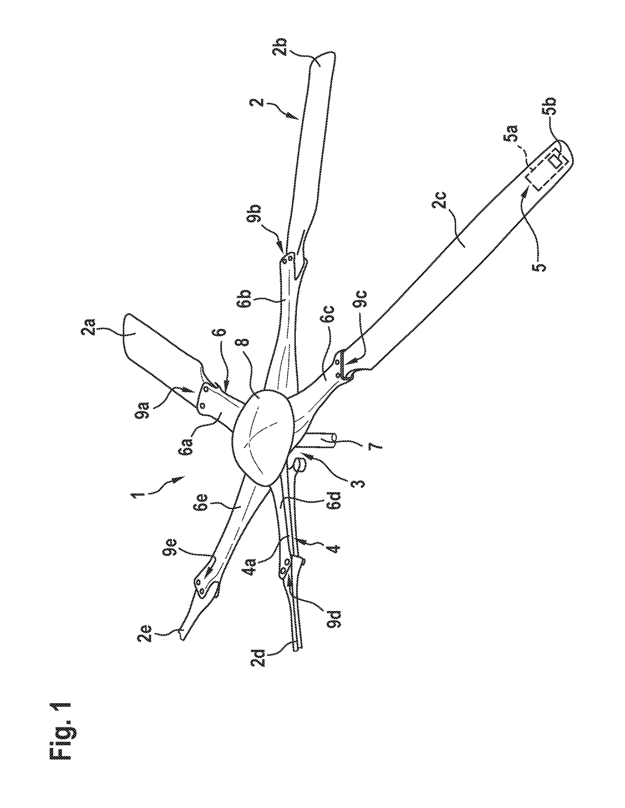
[0046]FIG. 1 shows a multi-blade rotor 1 of a rotary wing aircraft which can be used as main rotor of a helicopter according to one embodiment. By way of example, the multi-blade rotor 1 comprises a rotor head 3 which is arranged on a rotor mast 7 and illustratively covered by a rotor head cover 8. The rotor mast 7 forms a rotation axis of the multi-blade rotor 1 around which a plurality of rotor blades 2 rotate during operation.

[0047]By way of example, the multi-blade rotor 1 is embodied as a hinge- and bearingless rotor, wherein the plurality of rotor blades 2, which illustratively includes five rotor blades 2a, 2b, 2c, 2d, 2e, is preferably ...


PUM


Abstract

An extraction device for extracting a trim weight from a rotor blade, comprising a supporting tube that is at least partly provided with a female thread, and a threaded rod that is at least partially arranged in the supporting tube, wherein the threaded rod is coupled to a fixing element that is adapted for being detachably fixed to the trim weight and that is at least partially provided with a male thread which engages at least partially the female thread of the supporting tube, and wherein the threaded rod is at least partly plastically deformable.

Description

CROSS-REFERENCE TO RELATED APPLICATIONS[0001]This application claims priority to European patent application No. EP 16400013.5 filed on Apr. 25, 2016, the disclosure of which is incorporated in its entirety by reference herein.BACKGROUND OF THE INVENTION(1) Field of the Invention[0002]The invention relates to an extraction device for extracting a trim weight from a rotor blade. Moreover, the invention relates to a method for extracting a trim weight from a rotor blade using such an extraction device.(2) Description of Related Art[0003]Rotor blades of rotary wing aircrafts and, in particular, rotor blades of helicopters are usually provided with trim weights or masses to adjust the dynamic behavior of the rotor blades during operation and to avoid undesirable and hazardous vibrations. Due to the relatively high centrifugal forces acting upon the rotor blades during operation, as well as due to corrosion and underlying production conditions, such trim weights are usually clamped in th...

Claims


Application Information

Patent Timeline
Patent Type & Authority Applications(United States)
IPC IPC(8): B25B27/02B64C27/00B64C27/473B64F5/40
CPCB25B27/02B64C27/001B64C2027/005B64F5/40B64C27/473B25B23/0021
Inventor TANNHAEUSER, ALOIS
Owner AIRBUS HELICOPTERS DEUT GMBH
Why Eureka
Try Eureka