
Vehicle

a technology for vehicles and vehicles, applied in the field of vehicles, can solve the problems of long overall length, dramatic consequences, and inconvenient operation, and achieve the effect of convenient, safe and reliabl

Active Publication Date: 2017-02-14
FACTUAL +1
View PDF15 Cites 0 Cited by
  • Summary
  • Abstract
  • Description
  • Claims
  • Application Information

AI Technical Summary

Benefits of technology

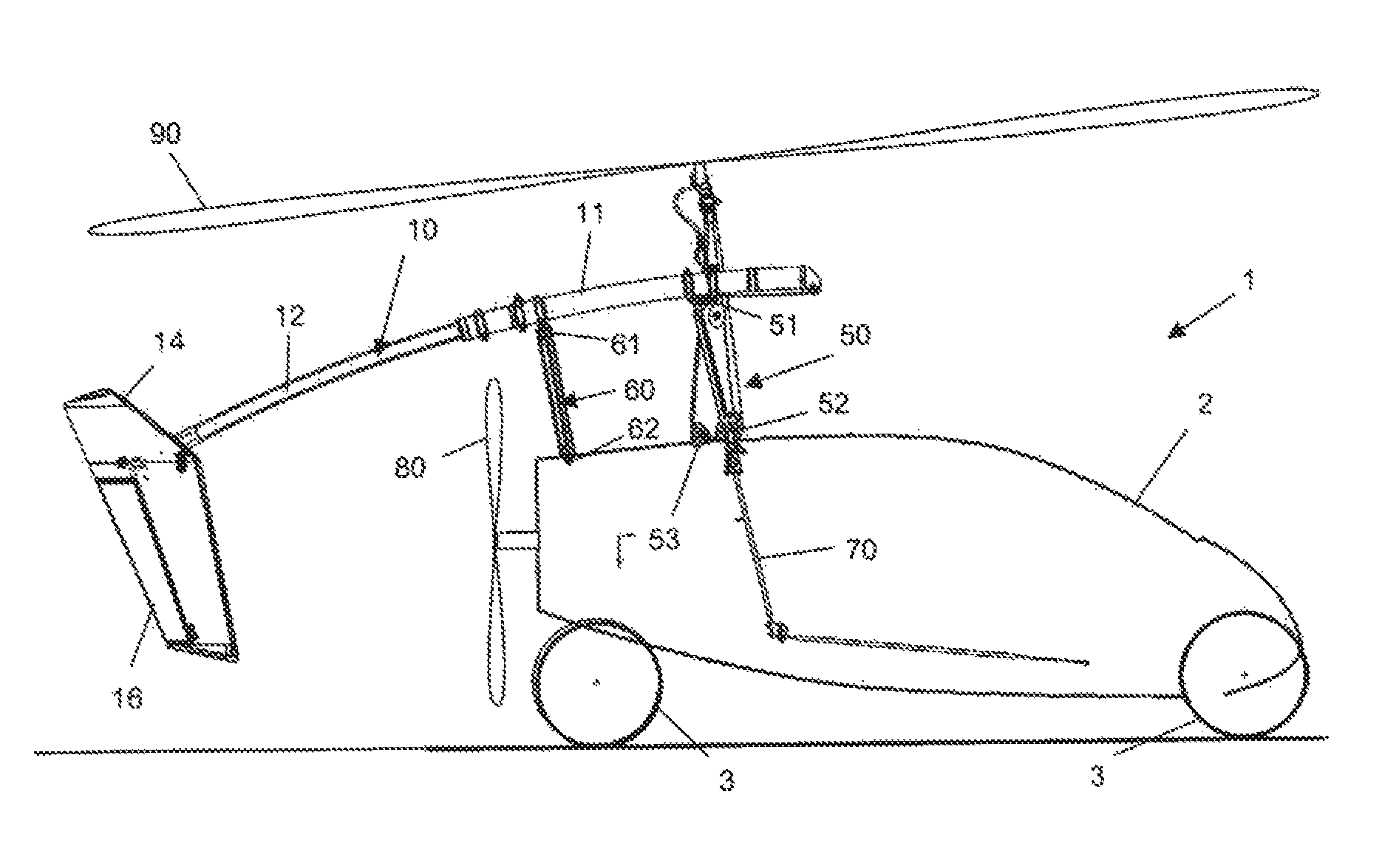
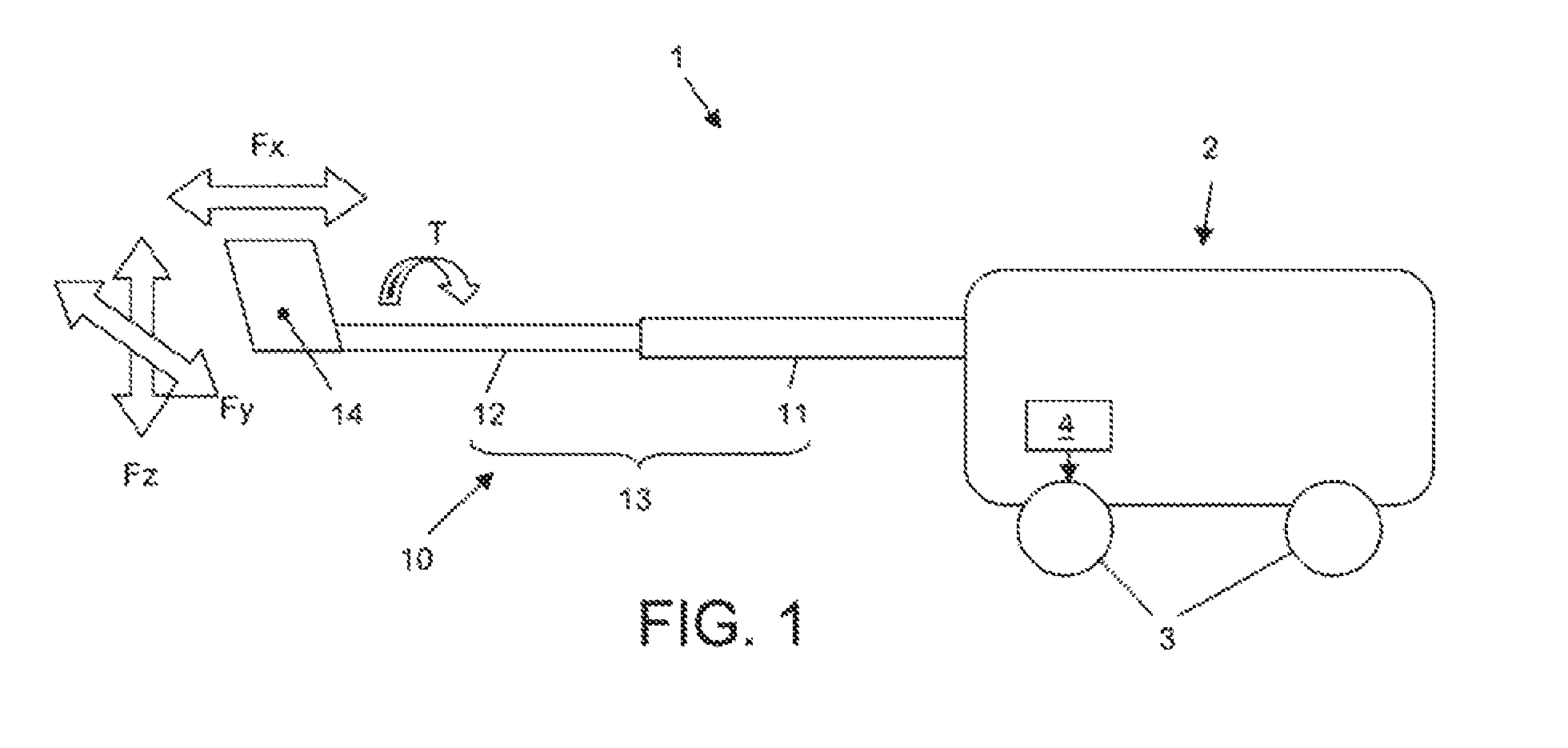
The present invention is related to a vehicle that can operate in both flying and driving modes. The design of the vehicle needs to meet the requirements for both modes and can easily change between them without compromising safety and reliability. The tail of the vehicle is designed to be extendable and retractable for transitioning between flying and driving modes, as well as for making parking or transporting the vehicle easier. The vehicle has a reinforced tail that can safely transfer forces and is designed to be easily handled by the user. The invention also includes a control cable arrangement for controlling the tail plane and foldable rotor blades for reducing space requirements during transport and / or storage.

Problems solved by technology

In the riding mode, such long tail is not needed, can be considered a hindrance, and it may even be that the overall length is too long with respect to traffic regulations.
When the user makes a mistake in extending the tail, the consequences can be dramatic if the tail is not fixed correctly.
When the tail is retracted, these cables are too long, and if the cables are not in a tightened state they sag and may become stuck in the mechanism.
One obvious solution might be to use an automatic roller for winding the excess length of cable, but this may lead to higher steering forces being needed and / or an increased risk of a cable getting stuck.

Method used


Image

  • Vehicle
  • Vehicle
  • Vehicle

Examples


Embodiment Construction

[0056]To facilitate an understanding of the principles and features of the various embodiments of the invention, various illustrative embodiments are explained below. Although exemplary embodiments of the invention are explained in detail, it is to be understood that other embodiments are contemplated. Accordingly, it is not intended that the invention is limited in its scope to the details of ingredients and arrangement of components set forth in the following description or illustrated in the drawing. The invention is capable of other embodiments and of being practiced or carried out in various ways. Also, in describing the exemplary embodiments, specific terminology will be resorted to for the sake of clarity.

[0057]It must also be noted that, as used in the specification and the appended claims, the singular forms “a,”“an” and “the” include plural references unless the context clearly dictates otherwise. For example, reference to an ingredient is intended also to include composit...


PUM


Abstract

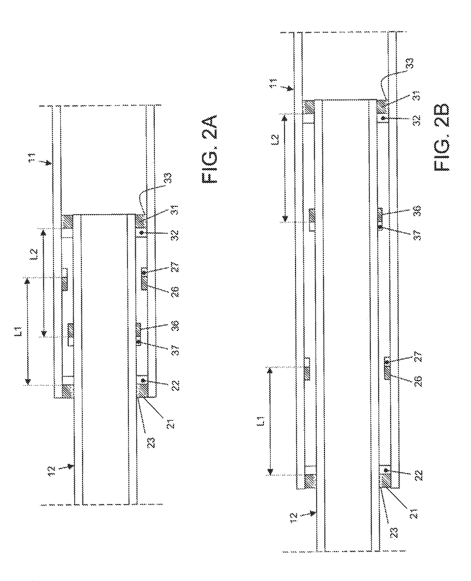
A vehicle capable of being converted between a flying condition and an automotive riding condition. The vehicle has a telescopically extendable tail having a first tubular tail segment and a second tail segment disposed axially slideable within the first tubular tail segment. The tail is provided with at least two form-closing coupling members located at an axial distance from each other for providing a force-transferring coupling between the second tail segment and the first tubular tail segment in the extended state of the second tail segment, each of the form-closing coupling members capable of transferring torque and transverse forces, and each of the form-closing coupling members coming into engagement by axial displacement of the second tail segment in the outward direction.

Description

CROSS-REFERENCE TO RELATED APPLICATIONS[0001]This application is a divisional of application Ser. No. 14 / 357,075, filed 8 May 2014, which is a US National Stage of International Application No. PCT / NL2012 / 000070, filed 9 Nov. 2012, which claims the benefit of NL Application 1039163, filed 11 Nov. 2011, each herein fully incorporated by reference in its entirety as if fully set forth below.BACKGROUND OF THE INVENTION[0002]1. Field of the Invention[0003]The present invention relates in general to a vehicle capable of flying in air.[0004]2. Description of Related Art[0005]Typically, it is customary for airplanes and helicopters to be either flying or standing on the ground, in a parking condition. Nevertheless, it is customary for airplanes and helicopters to have wheels, so that they can be displaced over ground, for instance towards and from a parking location. Airplanes and helicopters may even ride over land, for instance during take-off or landing or during taxiing: except during ...

Claims


Application Information

Patent Timeline
Patent Type & Authority Patents(United States)
IPC IPC(8): B64C1/26B64C27/02B64C27/06B64C1/30B64C1/06B60F5/02B64C27/50B64C37/00
CPCB60F5/02B64C1/063B64C1/26B64C1/30B64C27/02B64C27/06B64C27/50B64C37/00B64C27/52
Inventor STEKELENBURG, MICHAEL ALWIN WILLIAMKLOK, CHRISTIAAN CORNELISVAN RIJN, LOUIS PETRUS VALENTIJN MARIESOETHOUDT, WOUTER ADRIAANWEGERIF, ROBERT CHRISTIAAN
Owner FACTUAL
Learn More