Rod reducer instrument for spinal surgery

a technology of reducer and rod, which is applied in the field of surgical instruments, can solve the problems of difficult access, difficult access, and surgeons still being frequently faced with the task, and achieve the effect of reducing the rod

Active Publication Date: 2010-05-13
SPINAL ELEMENTS INC
View PDF17 Cites 110 Cited by
  • Summary
  • Abstract
  • Description
  • Claims
  • Application Information

AI Technical Summary

Benefits of technology

[0014]Certain embodiment can comprise a method of reducing a rod in orthopedic surgery. The method can comprise the steps of engaging a rod with a pushing member of a rod reducer instrument, the rod reducer further comprising a pliers and a handle, closing the pliers to grip an orthopedic screw and to form a threaded

Problems solved by technology

However, such access can be difficult depending on such factors as the malformation to be corrected and the overall physiology of the patient.
Additionally, as surgical procedures are generally encouraged to be minimally invasive, access can be very difficult as a result of the small ports or incisions of such procedures.
Additionally, with use of mono-axial screws, the physiology of the patient can require that the screw be placed at an angle such that the s

Method used


Image

  • Rod reducer instrument for spinal surgery
  • Rod reducer instrument for spinal surgery
  • Rod reducer instrument for spinal surgery

Examples


Embodiment Construction

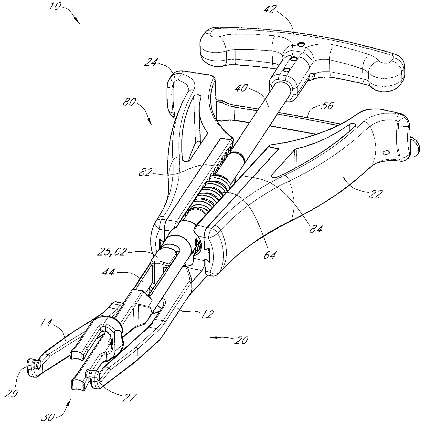
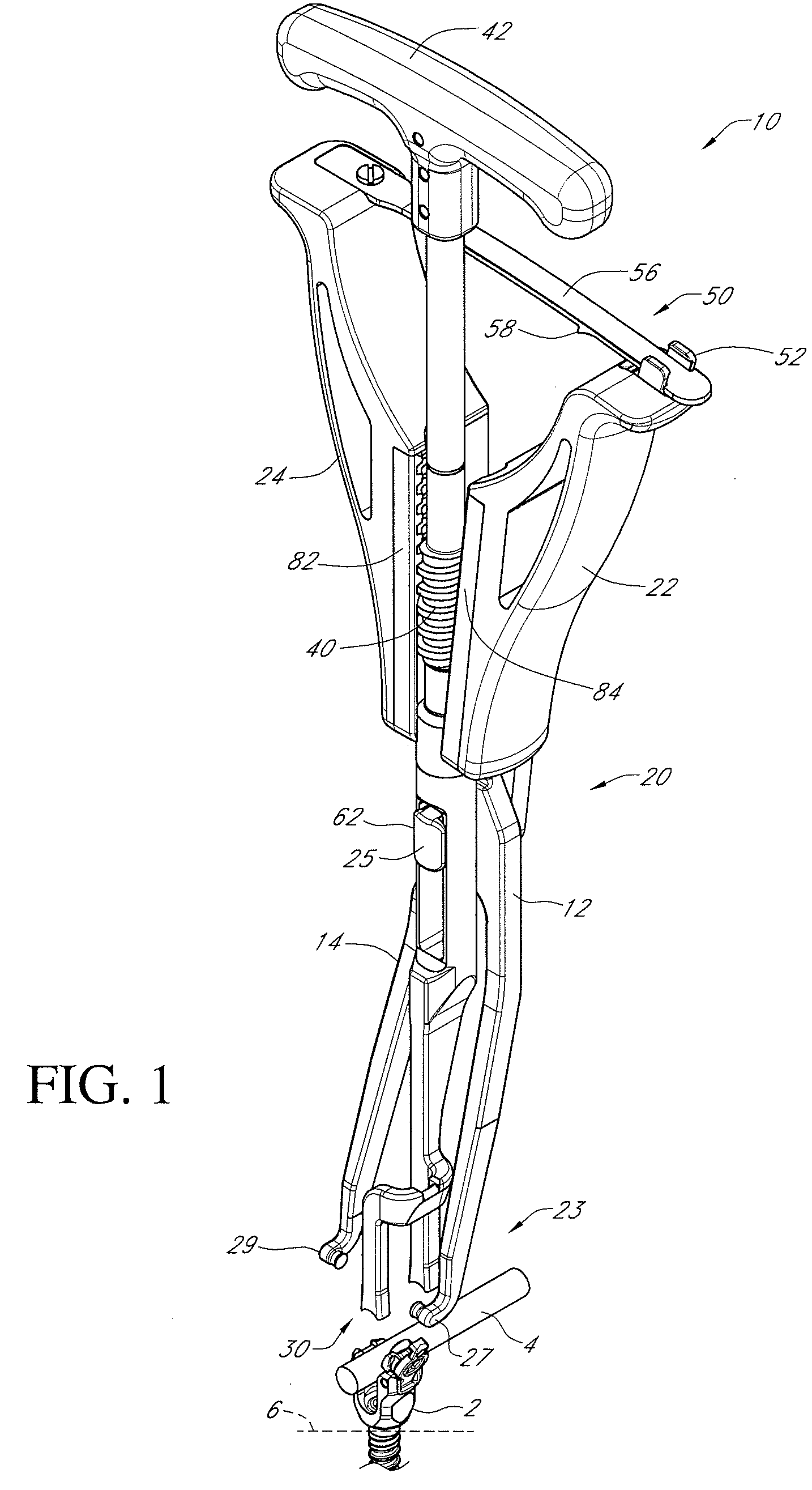
[0026]A rod reducer instrument 10 according to one embodiment is illustrated in FIG. 1. The rod reducer instrument or rod reducer 10 can be used to engage a fixation element 2 and a rod 4 to reduce the rod 4, or force the rod 4 into engagement with the fixation element 2.

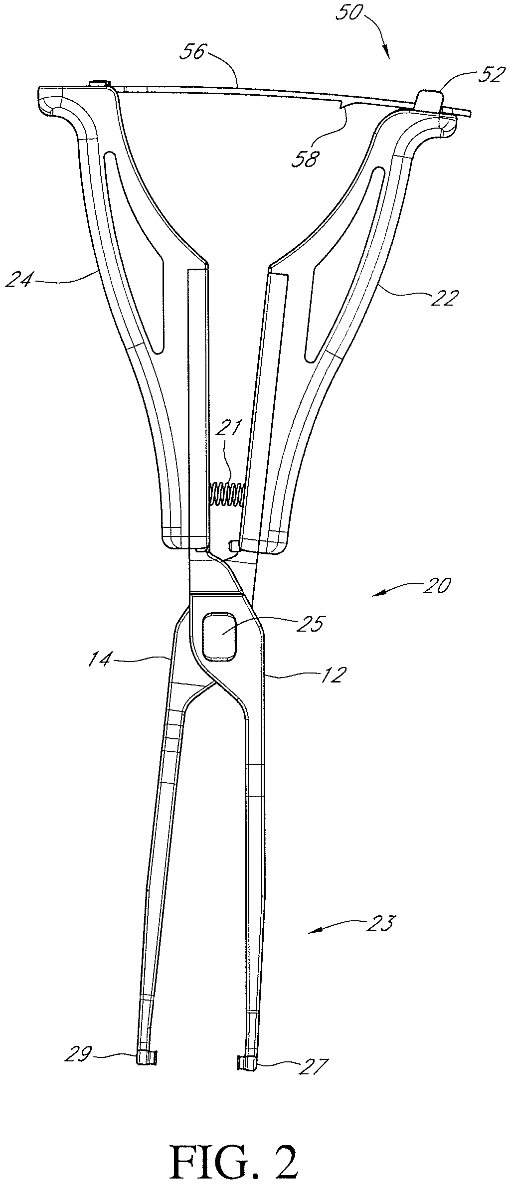
[0027]A simple overview of how a rod reducer instrument 10 according to one embodiment can be used will now be explained with reference to FIGS. 2-3. FIG. 2 shows a partially disassembled rod reducer 10 with a pliers 20 and some other features remaining. The pliers 20 can be used to engage and secure the rod reducer 10 to a fixation element 2, such as a bone screw. A pliers locking device 50 is also shown. The pliers locking device 50 can lock the pliers 20 in a closed position so that it is unnecessary for a user to continue to apply force to the pliers 20 to maintain the pliers 20 in the closed position. It is envisioned that a user may want to lock the pliers 20 in the closed position once the pliers 20 have been...


PUM


Abstract

A rod reducer instrument is configured to be secured to a fixation element and to force a rod into engagement with the fixation element. The rod reducer instrument can have a pliers to secure the rod reducer to the fixation element and a threaded shaft with a handle and a pusher member. The pliers can form a threaded channel that engages the threaded shaft and directs a movement of the shaft. The threaded shaft can translate a rotational movement at the handle into a linear movement at the pusher member and in this way force a rod into engagement with a fixation element.

Description

CROSS-REFERENCE TO RELATED APPLICATIONS[0001]N / ABACKGROUND OF THE INVENTION[0002]1. Field of the Invention[0003]The present invention concerns surgical instruments for moving one part of a surgical implant into adjacent position or contact with another. In particular, the invention contemplates rod reducer instruments for use in placing or moving an orthopedic rod toward a bone fixation element.[0004]2. Description of the Related Art[0005]In orthopedic surgery, and particularly in spinal surgery, it is well known to correct an injury, malformation, or other defect using an implanted rod affixed to a body part to be corrected. For example, rod systems have been developed for correcting the positioning of and stabilizing of the spine, and for facilitating fusion at various levels of the spine. In one such system, the rod or elongated implant can be disposed longitudinally along a length of the spine. The rod can be bent, either prior to or during surgery, to correspond to the normal c...

Claims


Application Information

Patent Timeline
IPC IPC(8): A61F5/00
CPCA61B17/7086
Inventor BLAIN, JASONKOVACH, ERICLAKE, MATT
Owner SPINAL ELEMENTS INC
Why Eureka
Try Eureka