Scalpel blade having dual indentations on back edge

a blade and back edge technology, applied in the field of blades, can solve the problems of brittle blades, severe hazards, and inability to adapt to the shape of blades,

Inactive Publication Date: 2010-05-20
ADITYA DISPOMED PRODS PRIVATE
View PDF28 Cites 7 Cited by
  • Summary
  • Abstract
  • Description
  • Claims
  • Application Information

AI Technical Summary

Problems solved by technology

Over time, different manufacturers used different fitment dimensions for the longitudinal hole in the scalpel blade and the protrusion on the handle, which made compatibility an issue.
Unfortunately, the greater the hardness of the blade, the more brittle the blade, which poses severe hazards if a blade breaks in vivo during surgery.

Method used


Image

  • Scalpel blade having dual indentations on back edge
  • Scalpel blade having dual indentations on back edge
  • Scalpel blade having dual indentations on back edge

Examples


first embodiment

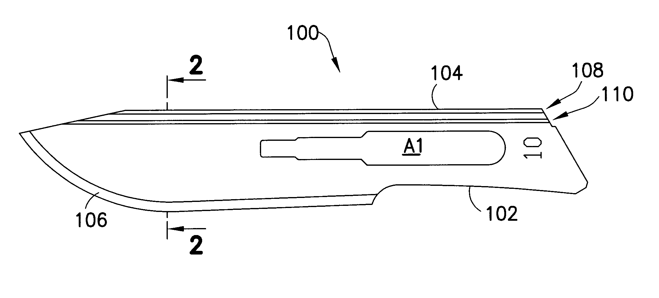
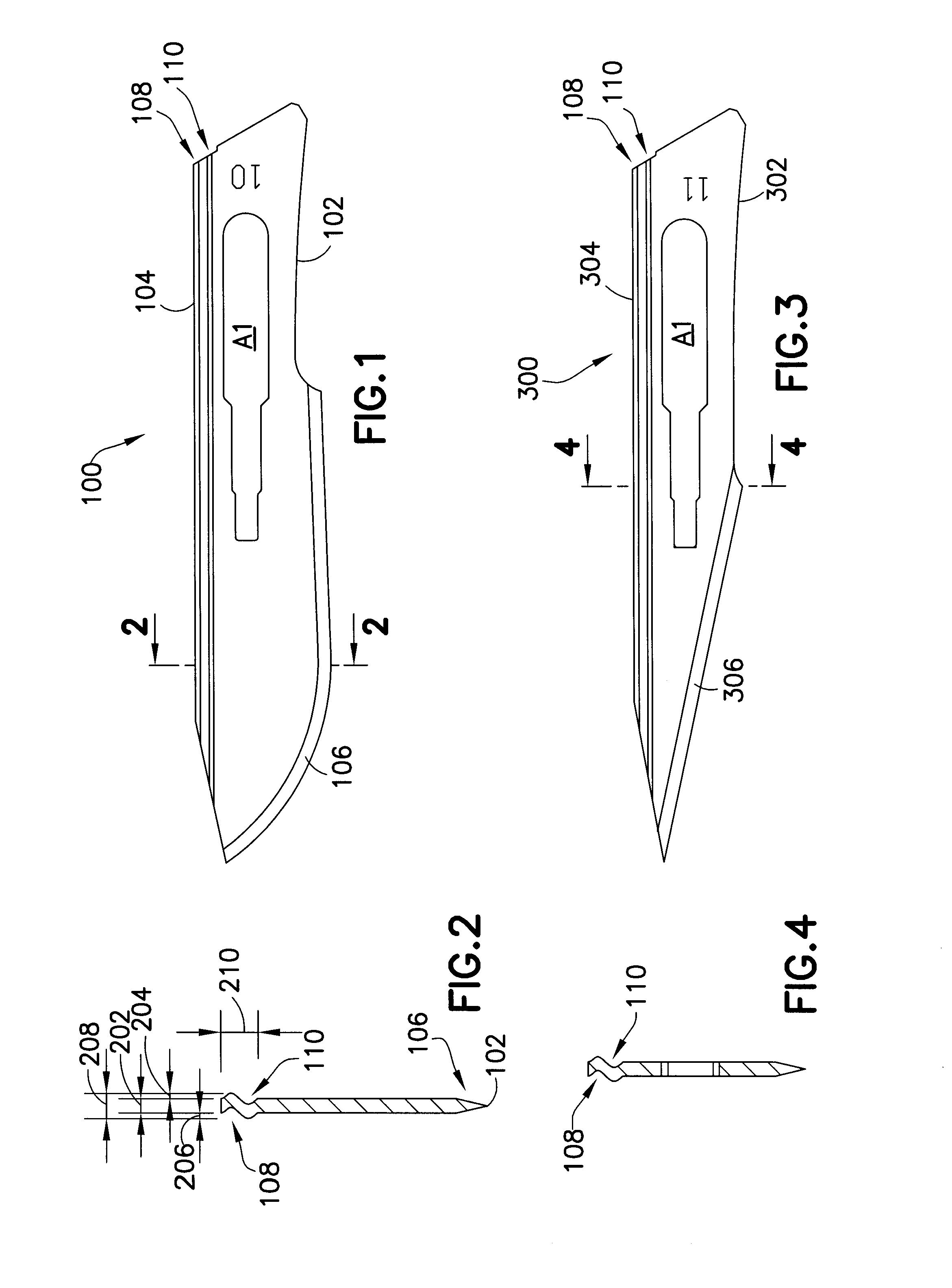
[0049]FIG. 1 is a profile view of the present invention, specifically, a number 10 scalpel blade. FIG. 2 is a cross-sectional view of the scalpel blade shown in FIG. 1.

[0050]As shown in FIG. 1, scalpel blade 100 preferably comprises first edge 102, second edge 104, cutting edge 106 located along a portion of first edge 102, first indentation 108 and second indentation 110. Second edge 104 is commonly referred to in the art as the back edge.

second embodiment

[0051]FIG. 3 illustrates a profile view of the present invention, specifically, a number 11 scalpel blade. As shown in FIG. 3, scalpel blade 300 preferably comprises first edge 302, second edge 304, cutting edge 306 located along a portion of first edge 302, first indentation 108 and second indentation 110. FIG. 4 is a cross-sectional view of the scalpel blade shown in FIG. 3.

third embodiment

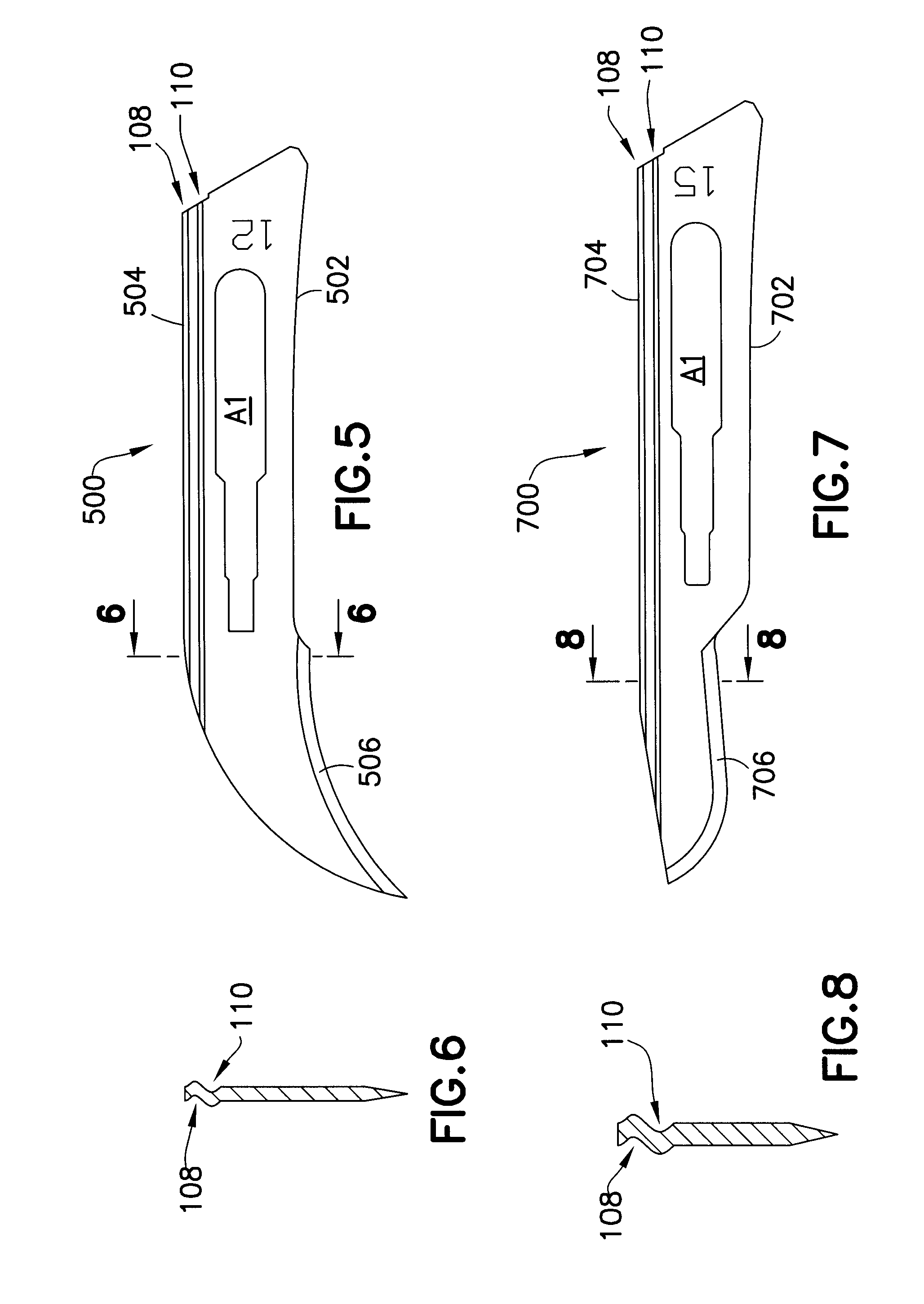
[0052]FIG. 5 illustrates a profile view of the present invention, specifically, a number 12 scalpel blade. As shown in FIG. 5, scalpel blade 500 preferably comprises first edge 502, second edge 504, cutting edge 506 located along a portion of first edge 502, first indentation 108 and second indentation 110. FIG. 6 is a cross-sectional view of the scalpel blade shown in FIG. 5.


PUM


Abstract

The present invention is directed to a scalpel blade having a longitudinal axis, the scalpel blade preferably comprising a first edge coincident with the longitudinal axis, a second edge coincident with the longitudinal axis, a cutting edge located along at least a portion of the first edge, and a first indentation in juxtaposition with and spanning at least a portion of the second edge, wherein the first indentation is offset in a first direction from the second edge. The scalpel blade preferably further comprises a second indentation in juxtaposition with and spanning at least a portion of the first indentation, wherein the second indentation is offset in a direction opposite from the second edge. The scalpel blade can either be removably attached to a reusable scalpel handle or indelibly attached to a disposable scalpel.

Description

BACKGROUND OF THE INVENTION[0001]1. Technical Field[0002]The present invention is directed to blades. More particularly, the present invention is directed to scalpel blades. The present invention finds particular utility in the medical field, as well as in applications that require a strong blade, that is, a blade able to withstand a large maximum load before failure.[0003]2. Background Information[0004]Various types of blades are known in the art. For example, in the field of arts and crafts, fine edged blades are used for cutting and shaping materials such as wood, balsa, cardboard, plastics, Bristol board, and the like. The use of scalpel blades in various applications is also well known.[0005]As understood by one skilled in the art, a scalpel comprises a scalpel handle and a scalpel blade. A scalpel blade is a relatively small and extremely sharp instrument used for surgery and anatomical dissections, as well as for various arts and crafts. Historically, a scalpel was comprised ...

Claims


Application Information

Patent Timeline
Patent Type & Authority Applications(United States)
IPC IPC(8): A61B17/32
CPCA61B17/3213
Inventor KEHR, RAJIV
Owner ADITYA DISPOMED PRODS PRIVATE
Why Eureka
Try Eureka