Molded object-forming apparatus and method

a technology of molded objects and molding apparatus, which is applied in the direction of turning apparatus, molds, food shaping, etc., can solve the problems of time-consuming and expensive processes

Inactive Publication Date: 2010-06-10
COMPIZED CUTTERS
View PDF33 Cites 4 Cited by
  • Summary
  • Abstract
  • Description
  • Claims
  • Application Information

AI Technical Summary

Problems solved by technology

This process is time-consuming and expensive.

Method used


Image

  • Molded object-forming apparatus and method
  • Molded object-forming apparatus and method
  • Molded object-forming apparatus and method

Examples


Embodiment Construction

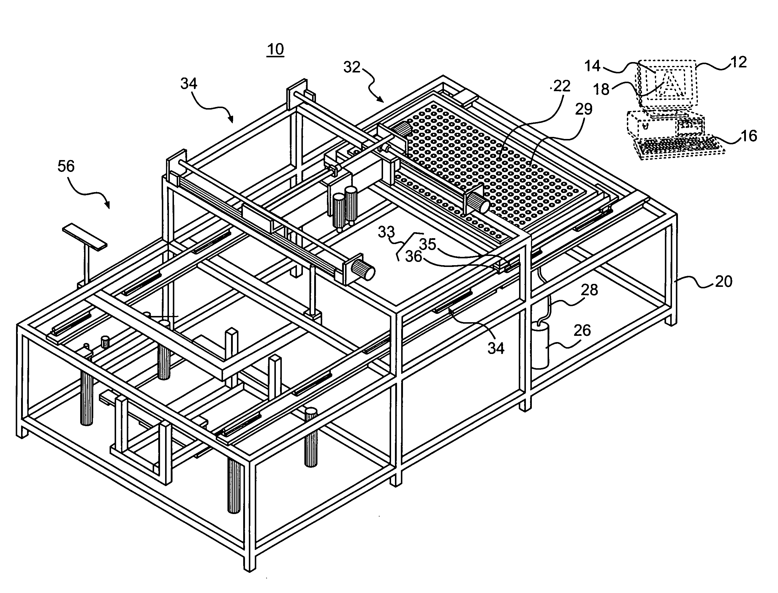
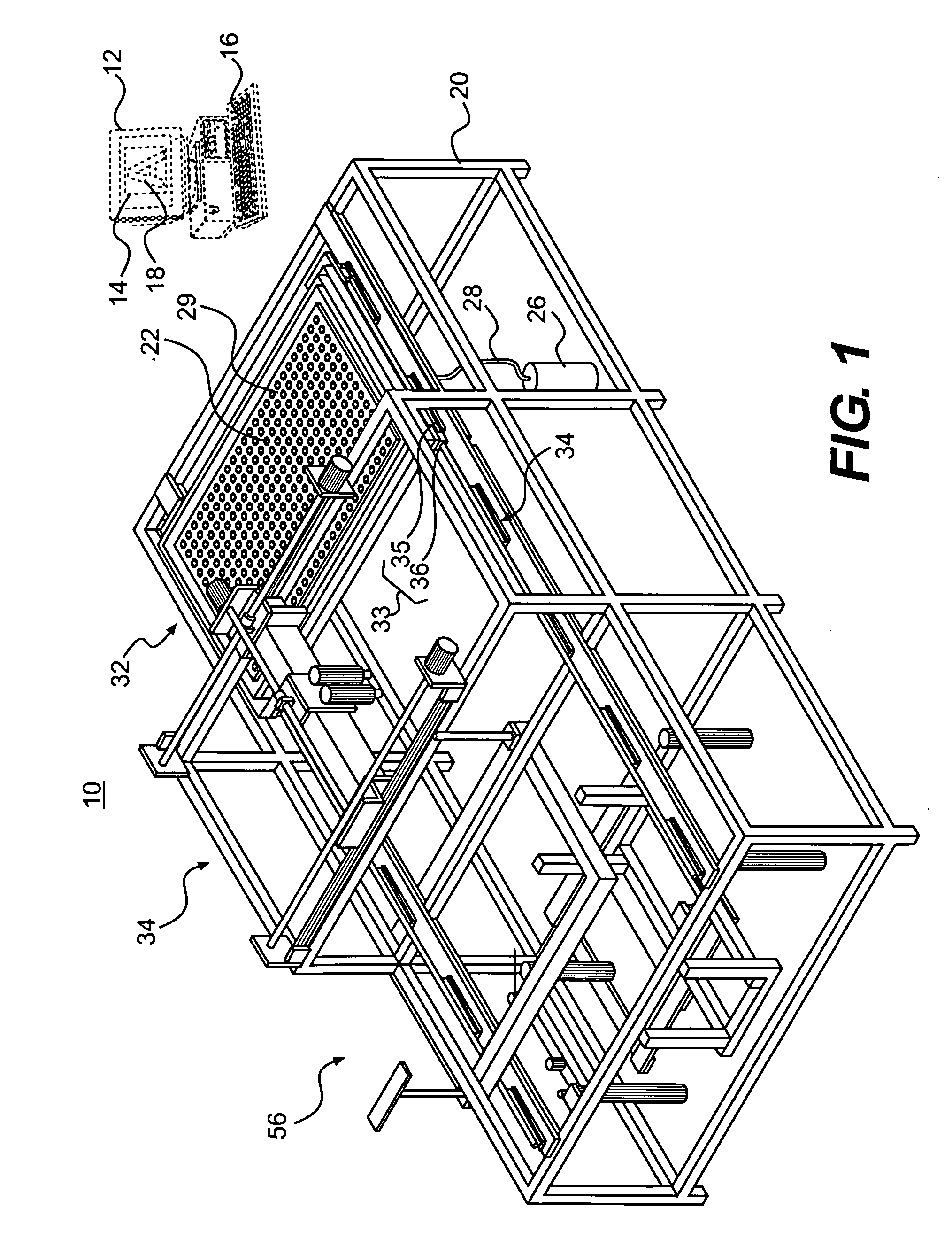
[0033]In accordance with the invention, and as broadly embodied in FIGS. 1-3, a molded-object forming apparatus 10 includes a processor 12 storing a shape of an object. Preferably, the processor 12 is a well-known commonly available desk-top computer, including a CPU (not shown), a memory, an LCD screen 14, and a keyboard 16, for inputting into the memory a shape of an object 18, e.g., a letter “A.”

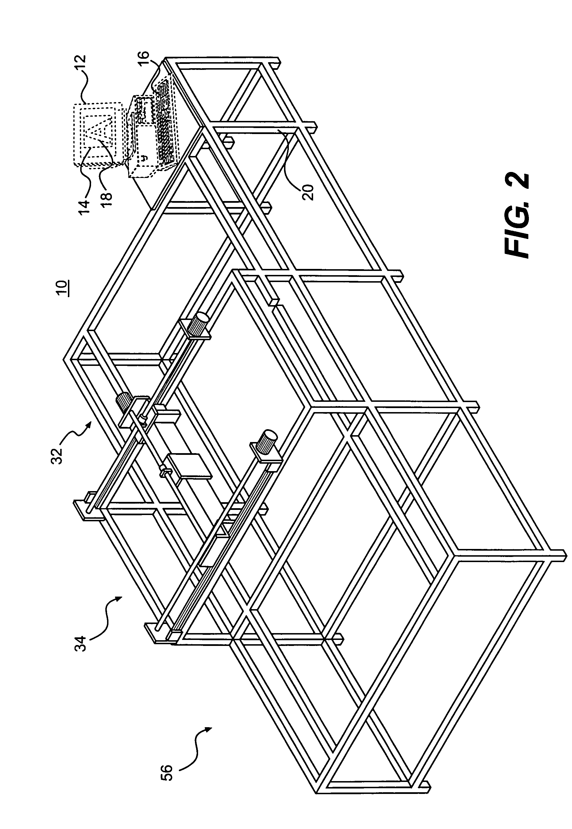
[0034]As broadly embodied herein, the apparatus 10 further includes a support frame 20, supporting a transfer table or table 22, movable between a plurality of table positions.

[0035]In accordance with the invention, and as broadly embodied in FIGS. 1 and 2, the processor 12 can be supported on the support frame 20, or at a provided remote location.

[0036]In accordance with the invention, a plurality of hydraulic pins is provided at each table position. A first set of hydraulic transfer pins 24 are provided at a first table position 32. When fired into corresponding apertures on table 22, t...


PUM

PropertyMeasurementUnit
shapeaaaaaaaaaa
movementaaaaaaaaaa
transparentaaaaaaaaaa

Abstract

An apparatus and method for forming a molded object, e.g., a channel letter trim and trimmed face. A shape is stored in a processor. A mold material is held by vacuum on a table, movably supported on a support frame. The table moves to a second position on the support frame, where the mold material is cut into a mold having the stored shape. The table and mold are moved to a third position on the support frame. Heated synthetic material is drawn over the mold by vacuum. After the synthetic material hardens, excess material is cut off, if necessary, and the synthetic material, now in the shape of the mold, is removed from the mold.

Description

FIELD OF THE INVENTION[0001]The present invention relates to a molded object-forming apparatus, and a method of forming a molded object. In particular, the molded object-forming apparatus, and the method relate to forming a molded synthetic trim cap for a channel letter.DESCRIPTION OF THE RELATED ART[0002]Three dimensional channel letters are well-known in the sign industry. A channel letter includes a three-dimensional letter or numeral-shaped “can,” typically made of thin sheet metal, closed at an end which faces the sign or wall, and open at another end which faces outward, with lights supported inside the “can,” and a transparent synthetic face or cap attached to the open end. The face or cap has the same letter or numeral shape as the can, with a flange for attaching the edges of the trim cap to the open end of the can. When the sign is turned on at night, light shines through the transparent faces or caps of the respective channel letters so the sign can be seen.[0003]Traditio...

Claims


Application Information

Patent Timeline
Patent Type & Authority Applications(United States)
IPC IPC(8): B28B7/14
CPCB29C51/10B29C2791/006B29C51/261B29C51/20
Inventor ONDRACEK, CARL
Owner COMPIZED CUTTERS
Why Eureka
Try Eureka