Foam-core golf balls

a golf ball and foam core technology, applied in the field of foam core golf balls, can solve the problems of high spin rate golf balls, increased compression, and recreational players who cannot intentionally control the spin of golf balls

Inactive Publication Date: 2010-06-10
ACUSHNET CO
View PDF69 Cites 9 Cited by
  • Summary
  • Abstract
  • Description
  • Claims
  • Application Information

AI Technical Summary

Benefits of technology

[0009]The present invention is directed to a golf ball with a controlled moment of inertia and controlled spin rate. The moment of inertia is preferably controlled by a reduction in the specific gravity or weight of an intermediate layer, e.g., by foaming. Depending on

Problems solved by technology

As the resiliency increases, however, the compression also increases making a harder ball, which is undesirable.
On the other hand, recreational players who cannot intentionally control the spin of the ball generally do not prefer a high spin rate golf ball.
When a club head strikes a ball, an unintention

Method used


Image

  • Foam-core golf balls
  • Foam-core golf balls
  • Foam-core golf balls

Examples


Embodiment Construction

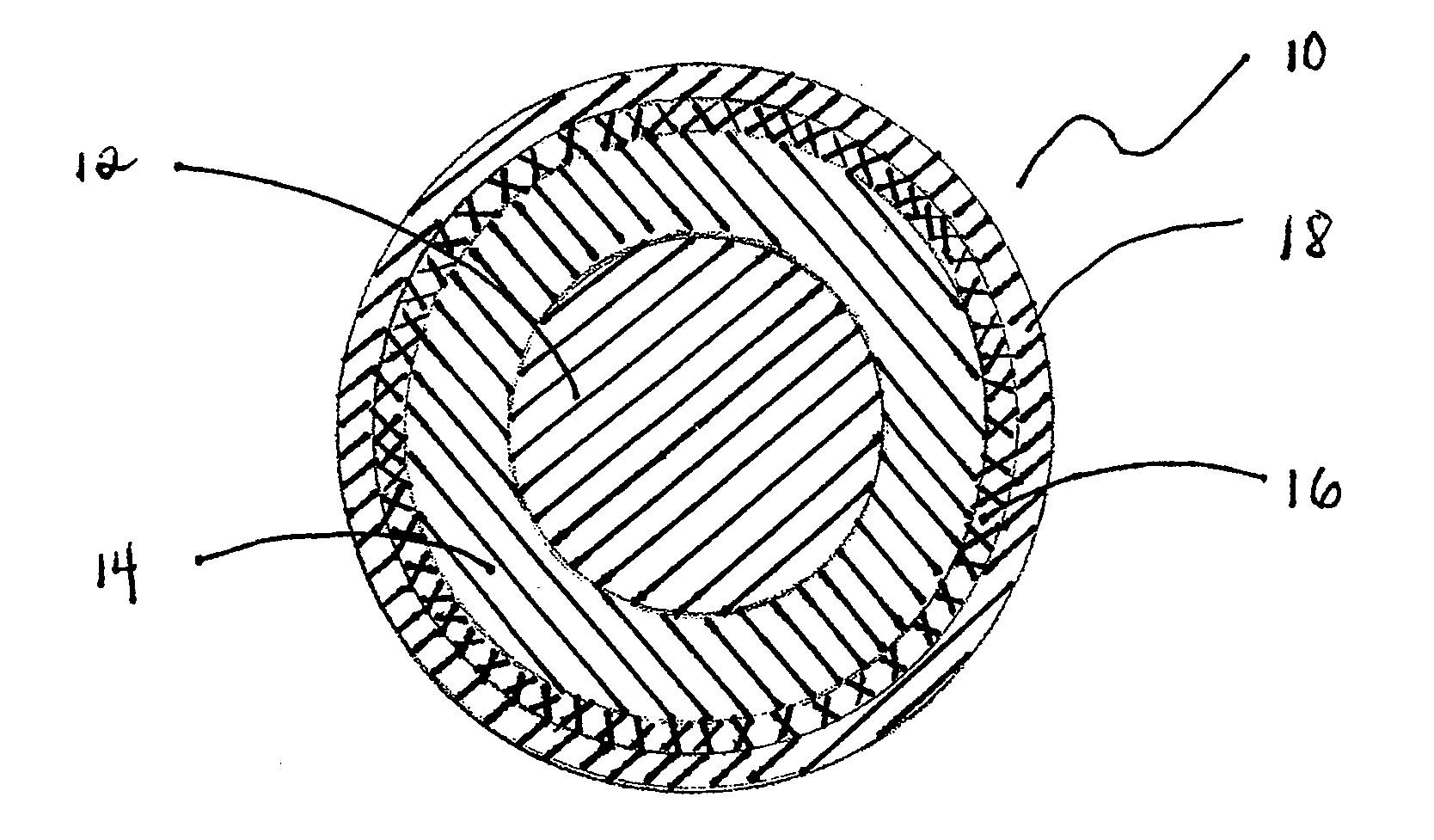
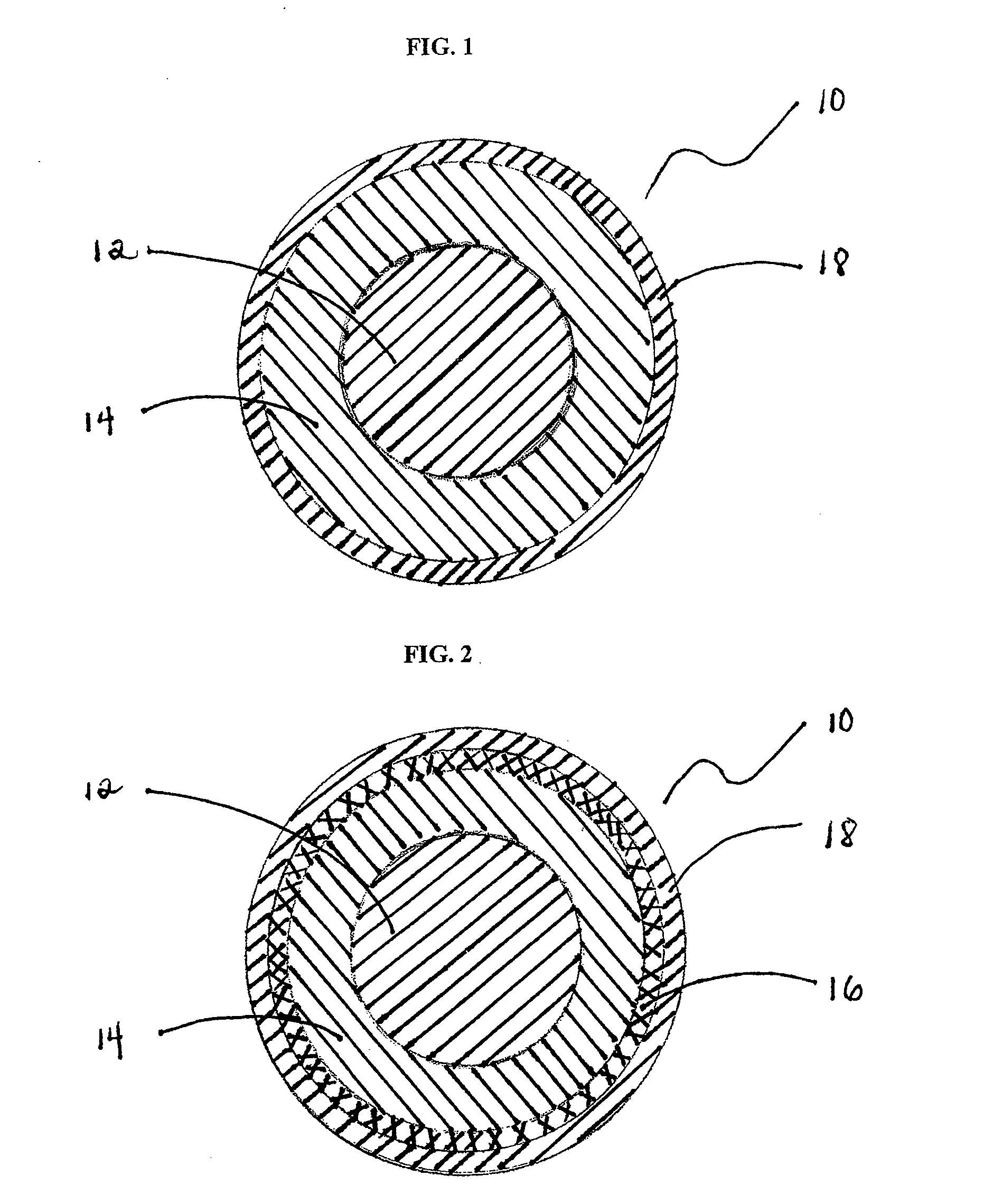
[0013]It is well known that the total weight of the ball has to conform to the weight limit set by the United States Golf Association (“USGA”). Redistributing the weight or mass of the ball either toward the center of the ball or toward the outer surface of the ball changes the dynamic characteristics of the ball at impact and in flight. Specifically, if the density is shifted or redistributed toward the center of the ball, the moment of inertia is reduced, and the initial spin rate of the ball as it leaves the golf club would increase due to lower resistance from the ball's moment of inertia. Conversely, if the density is shifted or redistributed toward or within the outer cover, the moment of inertia is increased, and the initial spin rate of the ball as it leaves the golf club would decrease due to the higher resistance from the ball's moment of inertia. The radial distance from the center of the ball or from the outer cover, where the moment of inertia switches from being increa...


PUM


Abstract

A golf ball with a controlled moment of inertia and controlled spin rate is disclosed. In one embodiment, the golf ball comprises a core, an intermediate layer and a cover, wherein the intermediate layer comprises a foamed highly neutralized polymer, has its specific gravity reduced to less than about 1.05, wherein the reduction in the specific gravity of the intermediate layer is less than about 25% to minimize the reduction in the coefficient of restitution of the golf ball to about 6% or less.

Description

CROSS-REFERENCE TO RELATED APPLICATIONS[0001]The present application is a divisional of co-pending U.S. patent application no. 11 / 284,382 filed Nov. 21, 2005, which is related to U.S. patent applications as follows. A continuation-in-part of co-pending U.S. patent application Ser. No. 11 / 191,087 filed Jul. 27, 2005, now U.S. Pat. No. 7,452,291, and a continuation-in-part of co-pending U.S. patent application Ser. No. 10 / 974,144 filed on Oct. 27, 2004, abandoned, which is a continuation-in-part of U.S. Pat. No. 6,852,042. Also, a continuation-in-part of co-pending U.S. patent application Ser. No. 10 / 440,984, filed May 19, 2003, now U.S. Pat. No. 6,995,191. Furthermore, a continuation-in-part of co-pending U.S. patent application Ser. No. 11 / 101,207 filed Apr. 7, 2005, now U.S. Pat. No. 7,211,007, which is a continuation-in-part of U.S. Pat. No. 6,929,567. Meanwhile, a continuation-in-part of co-pending U.S. patent application Ser. No. 11 / 061,260 filed Feb. 18, 2005, now U.S. Pat. No....

Claims


Application Information

Patent Timeline
IPC IPC(8): A63B37/00A63B37/02
CPCA63B37/0003A63B37/0045A63B37/0047A63B37/0064A63B37/0066A63B37/0076A63B37/0039A63B37/0041A63B37/0058A63B37/0061A63B37/0078
Inventor SULLIVAN, MICHAEL J.LADD, DEREK A.HERBERT, EDMUND A.
Owner ACUSHNET CO
Why Eureka
Try Eureka