Flexible electronic assembly and method of manufacturing the same

a printed circuit and electronic assembly technology, applied in semiconductor devices, lighting and heating apparatus, light source devices, etc., can solve the problems of complex combined pcb-flex manufacturing process, low flexibility of flexible printed circuits, and inability to optimize multi-component systems for size and weight parameters

Active Publication Date: 2014-09-18
SUMITOMO ELECTRIC PRINTED CIRCUITS INC +1
View PDF2 Cites 140 Cited by
  • Summary
  • Abstract
  • Description
  • Claims
  • Application Information

AI Technical Summary

Benefits of technology

[0018]Herein, identical reference numerals are used, where possible, to designate identical elements that are common to

Problems solved by technology

However, as more layers of metal and non-conductive substrates are added to the sandwich, the flexible printed circuit becomes less flexible.
In addition, attempts to add electrical or electronic devices require the mounting of components onto the surfaces of the flexible circuit.
As a result, the multi-component system is not optimized for size and weight parameters.
Furthermore, the combined PCB-flex manufacturing processes are complex and expensive.
The process for mounting SMDs is likewise complex and less cost effective.
For example, over-molding of devices such as semiconductor circuits, requires additional assembly and packaging process steps.
In addition, the aforementioned PCB substrates, rigid-flex substrates, and flexible substrates are poor conductors of heat.
Therefore, when heat generated by the mounted device is excessive, e.g., in the case of power circuits, microprocessors, and light-emitting devices, more expensive thermally conductive substrates accompanied with the attachment of a bulky conducting heat sink are required.
Without the a

Method used


Image

  • Flexible electronic assembly and method of manufacturing the same
  • Flexible electronic assembly and method of manufacturing the same
  • Flexible electronic assembly and method of manufacturing the same

Examples


Embodiment Construction

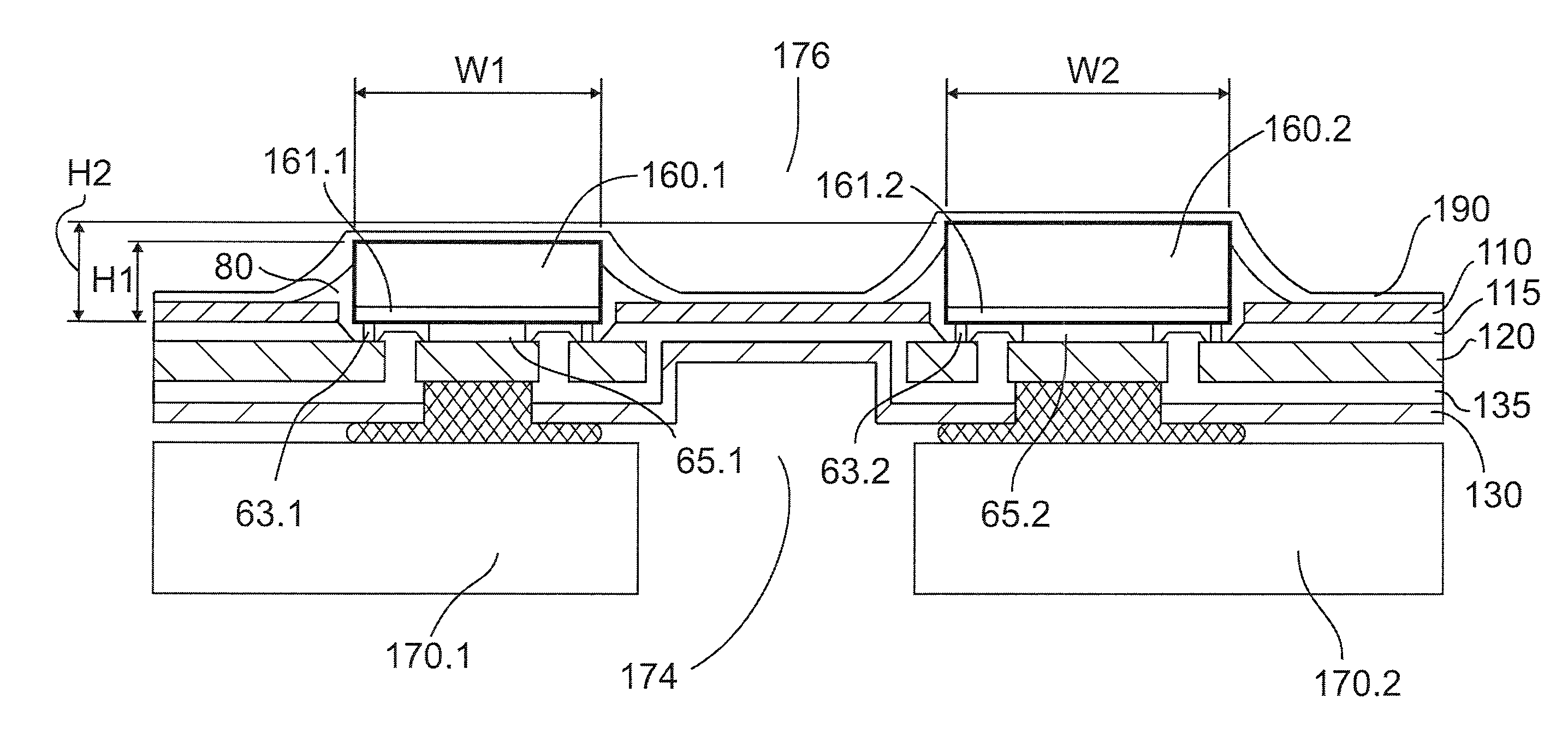
[0007]According to a first aspect of the present invention, a flexible circuit assembly for accommodating a plurality of power electronic devices is provided. Preferably, the flexible circuit assembly includes an insulating cover layer having first openings, the first openings configured to receive the plurality of power electronic devices at least partially inside the first openings, a flexible conductive layer arranged under the insulating cover layer and attached with a first adhesive to the insulating cover layer, the flexible conductive layer having a plurality of islands and conductive traces, the first openings arranged above the islands, and an intermediate insulating layer arranged under the flexible conductive layer and attached with a second adhesive to the flexible conductive layer, the intermediate insulating layer having second openings, the second openings arranged below the islands. Moreover, the flexible circuit assembly preferably further includes a plurality of he...


PUM

PropertyMeasurementUnit
Lengthaaaaaaaaaa
Lengthaaaaaaaaaa
Thicknessaaaaaaaaaa

Abstract

A flexible circuit assembly for accommodating a plurality of power electronic devices, including an insulating cover layer having first openings for power electronic devices, a flexible conductive layer arranged under the insulating cover layer and attached with a first adhesive to the insulating cover layer, an intermediate insulating layer arranged under the flexible conductive layer and attached with a second adhesive to the flexible conductive layer, the intermediate insulating layer having second openings, a plurality of heat-conductive elements arranged inside the second openings, a first thin heat sink layer, the heat-conductive elements arranged to be in contact with an upper surface of the thin heat sink layer and the lower surface of the islands via heat-conductive material; and a second thin heat sink layer, upper surfaces of the power electronic devices arranged to be in contact with a lower surface of the thin heat sink layer and the lower surface of the islands via heat-conductive material.

Description

TECHNICAL FIELD OF THE INVENTION[0001]The present invention relates generally to flexible printed circuit assemblies that can be bent and rolled (including flexible printed circuit assemblies that comprise power electric devices), a method of embedding such power electronic devices into flexible printed circuits of the flexible printed circuit assemblies, and a method of providing an automatic manufacturing process to generate bendable and rollable power electronic assemblies.BACKGROUND OF THE INVENTION[0002]Flexible printed circuits and rigid-flexible printed circuits are used in many applications where at least certain parts of the circuits need to be installed in a bent state. Flex circuitry incorporates metal lines sandwiched between non-conductive flexible layers of the flexible printed circuit. However, as more layers of metal and non-conductive substrates are added to the sandwich, the flexible printed circuit becomes less flexible. In addition, attempts to add electrical or ...

Claims


Application Information

Patent Timeline
IPC IPC(8): F21V19/00F21K99/00H05K3/30H05K1/02
CPCF21V19/003F21K9/00H05K3/306H05K1/028F21K9/90H05K1/0206H05K1/189H05K3/0061H05K2201/051H05K2201/10106F21S4/22F21S4/24Y10T29/49139H05K2203/1545
Inventor WANG, JAMES JEN-HOPARK, JIN JOO
Owner SUMITOMO ELECTRIC PRINTED CIRCUITS INC
Why Eureka
Try Eureka