Method for characterizing a feature on a mask and device for carrying out the method

Active Publication Date: 2012-03-29
CARL ZEISS SMT GMBH
View PDF4 Cites 28 Cited by
  • Summary
  • Abstract
  • Description
  • Claims
  • Application Information

AI Technical Summary

Benefits of technology

[0035]In some examples, a direct total intensity is determined by acquiring an individual intensity by means of a high-sensitivity non-imaging sensor. This has the advant

Problems solved by technology

Another problem is that the mask features are known and are optimized by resolution enhancement technology (RET), and thus do not

Method used


Image

  • Method for characterizing a feature on a mask and device for carrying out the method
  • Method for characterizing a feature on a mask and device for carrying out the method
  • Method for characterizing a feature on a mask and device for carrying out the method

Examples


Embodiment Construction

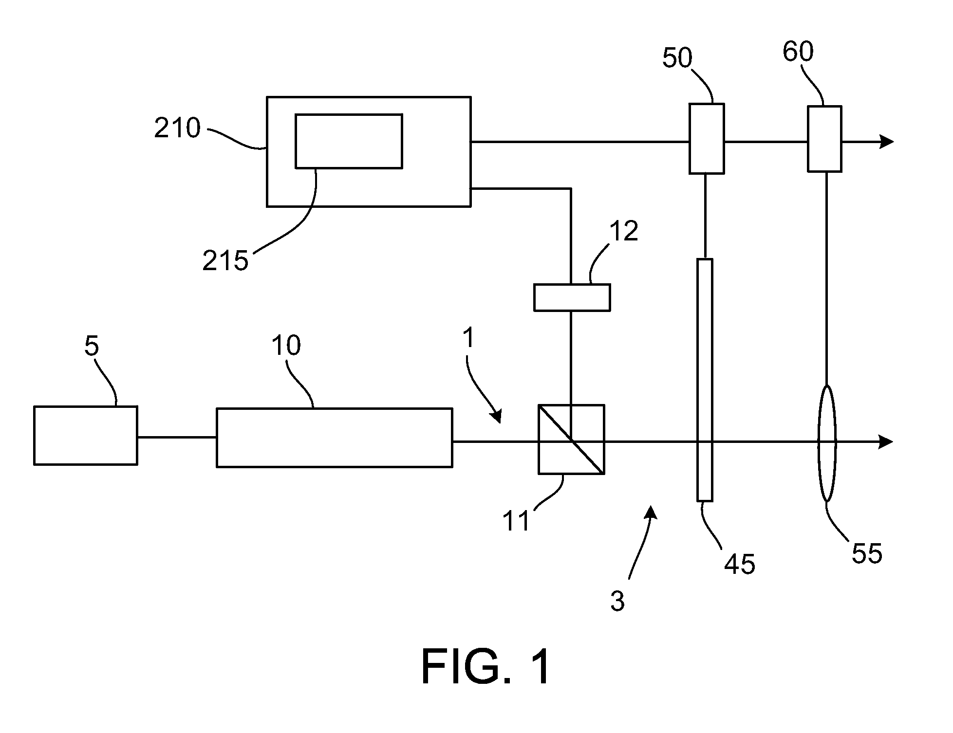
[0047]A mask inspection microscope according to a first exemplary embodiment includes, as illustrated in FIG. 1, a radiation source 5, such as an excimer laser that emits illuminating radiation at a wavelength of 193 nm. Next along an optical axis 1 is a homogenizer 10 for homogenizing the intensity distribution of the illuminating radiation in a pupil plane and depolarizing the illuminating radiation. A beam splitter 11 diverts a portion of the illuminating radiation to an energy monitor 12. Time variations of the intensity of the radiation source 5 are recorded by a data processing system 210.

[0048]Next is a stop plate 45, which is disposed in a pupil plane of the illumination beam path 3. This serves to configure an illumination setting, such as dipole or annular, for example. A drive 50 provides precise control of the position of the stop plate 45.

[0049]An adjusted aperture of the stop plate 45 is imaged by a zoom lens 55 with an actuator 60 in the desired size on a resultant pu...


PUM


Abstract

A mask inspection microscope is provided for characterizing a mask having a feature. The mask inspection microscope is configured to generate an aerial image of at least one segment of the feature of the mask, acquire a spatially resolved intensity distribution of the aerial image, and determine a total intensity from the intensities of at least one region of the aerial image.

Description

CROSS REFERENCE TO RELATED APPLICATIONS[0001]Pursuant to 35 U.S.C. §119, this application claims the benefit of U.S. provisional application 61 / 387,514, filed on Sep. 29, 2010, and German application DE 10 2010 047 050.3, filed on Sep. 29, 2010, both of which are incorporated by reference.BACKGROUND OF THE INVENTION[0002]This subject matter is generally directed to a method and a mask inspection microscope for characterizing a feature on a mask.[0003]In the fabrication of semiconductor components, numerous measurement methods are used to monitor the results of the individual steps in the lithographic process.[0004]To verify a process for generating features on wafers, it is advantageous to characterize the smallest features that can still be formed on a wafer. These are referred to as the critical dimension, abbreviated CD. The critical dimension of a feature usually refers to the line width of a feature composed of alternating lines and spaces. In the lithographic process, this fea...

Claims


Application Information

Patent Timeline
IPC IPC(8): G06K9/00H04N7/18
CPCG01B11/02G03F1/84G01N2021/95676G01N21/95607
Inventor SEITZ, HOLGER
Owner CARL ZEISS SMT GMBH
Why Eureka
Try Eureka