
Method for enhancing polarimeter systems that use micro-polarizers

Inactive Publication Date: 2008-07-10
LOCKHEED MARTIN CORP
View PDF5 Cites 28 Cited by
  • Summary
  • Abstract
  • Description
  • Claims
  • Application Information

AI Technical Summary

Benefits of technology

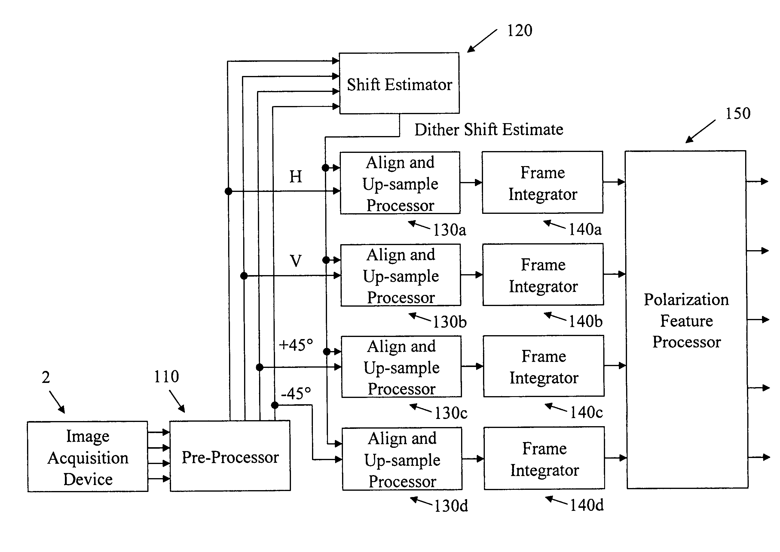
[0016]A preferred embodiment of the invention overcomes the problem of under-sampling of each of the polarization images (and the resulting aliasing noise) using a dithered frame-integration approach that allows the PSF to be matched to the individual detector element size, thus providing near-optimum resolution and SNR. The integrated polarization images produced are Nyquist-sampled with sample points corresponding to the centers of all of the individual detectors, so that the registration of one polarization image to another is simplified (e.g. a unit-pixel shift in x and / or y direction(s)). The registration is essentially perfect and the SNR is greatly improved, both by the smaller PSF and by the effects of integration. The number of pixels in each of the resulting polarized images is the total number of individual detector elements, so that the full vector complement of polarimetric information is available for each pixel position.

Problems solved by technology

One such challenge is distinguishing targets from the surrounding / background environment.
On the other hand, detection algorithms that discriminate targets from background on the basis of target intensity can produce false detections due to the presence of particularly hot or cold objects, including fires or heated objects.
Construction of high-quality polarization imagery data is not without challenges.
The process of separating and processing the responses to the polarized components of light can produce images that suffer from poor signal-to-noise ratio (SNR), poor polarization isolation, and inaccurate registration of the multiple polarization images with respect to one another.
However, time delays between each polarization may cause polarization registration issues if either the target or the detector is moving.
In addition, registration of the individual polarization components may be challenging, especially over temperature variations and mechanical vibration.
This type of system is also expensive and bulky; however, the amplitude division method does provide good resolution and minimal motion artifacts, since all polarizations are derived simultaneously.
In many applications, the polarimetric imagery acquisition methods described above yield inadequate SNR.
All of the methods described above sacrifice resolution and / or registration stability or accuracy.
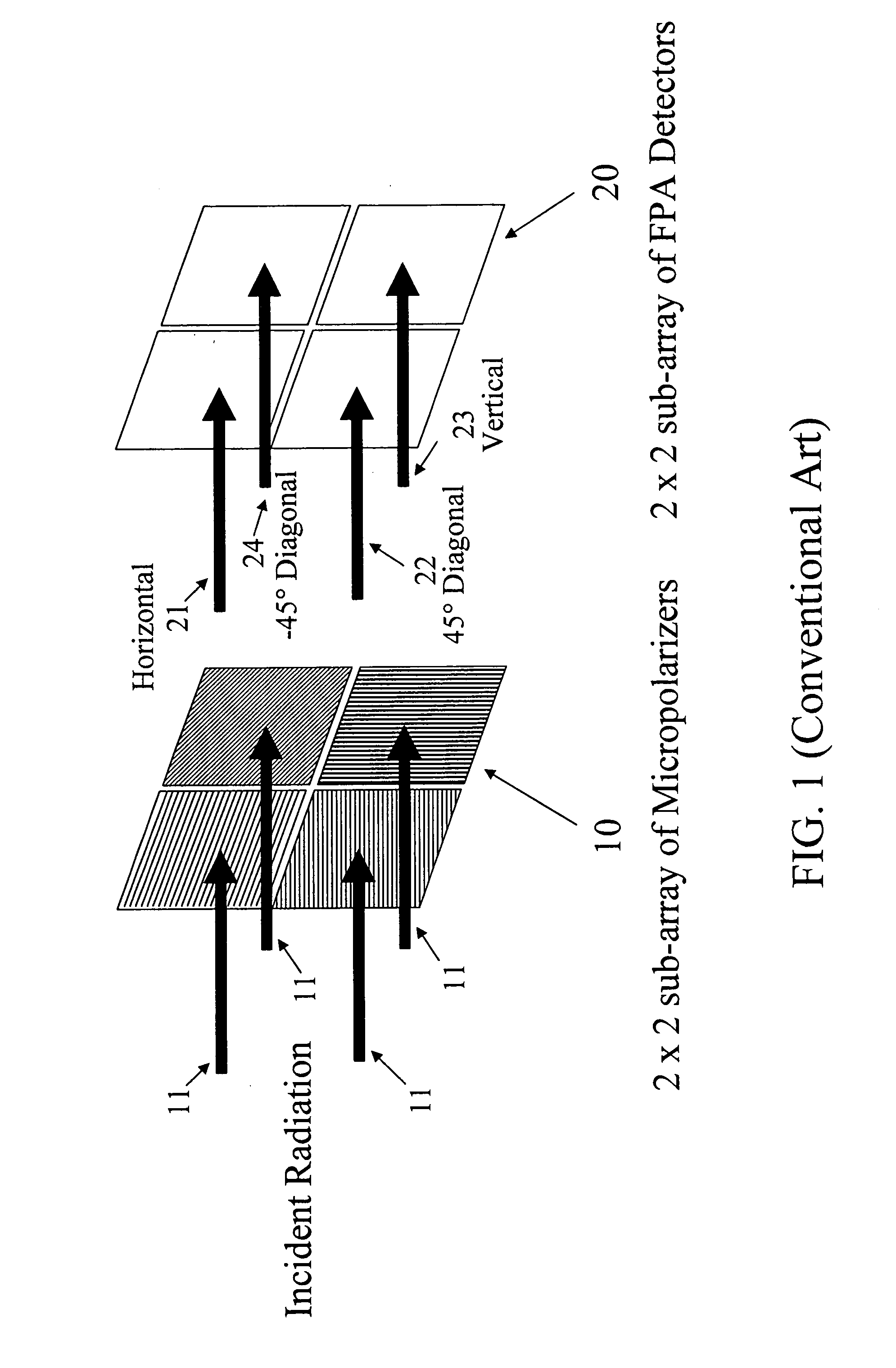
However, the conventional system design using the micro-polarizer FPA suffers from less than optimum resolution and an additional SNR loss, since the PSF is sized to illuminate four pixels in order to obtain all polarization measurements.
This results in degradation of resolution by factor of 2 in each spatial direction and reduction of SNR by factor of 4 in addition to the necessary loss of energy due to the polarizing filters.

Method used


Image

  • Method for enhancing polarimeter systems that use micro-polarizers
  • Method for enhancing polarimeter systems that use micro-polarizers
  • Method for enhancing polarimeter systems that use micro-polarizers

Examples


Embodiment Construction

[0028]The following detailed description of the invention refers to the accompanying drawings. The same reference numbers in different drawings identify the same or similar elements. Also, the following detailed description does not limit the invention. Instead, the scope of the invention is defined by the appended claims and equivalent thereof.

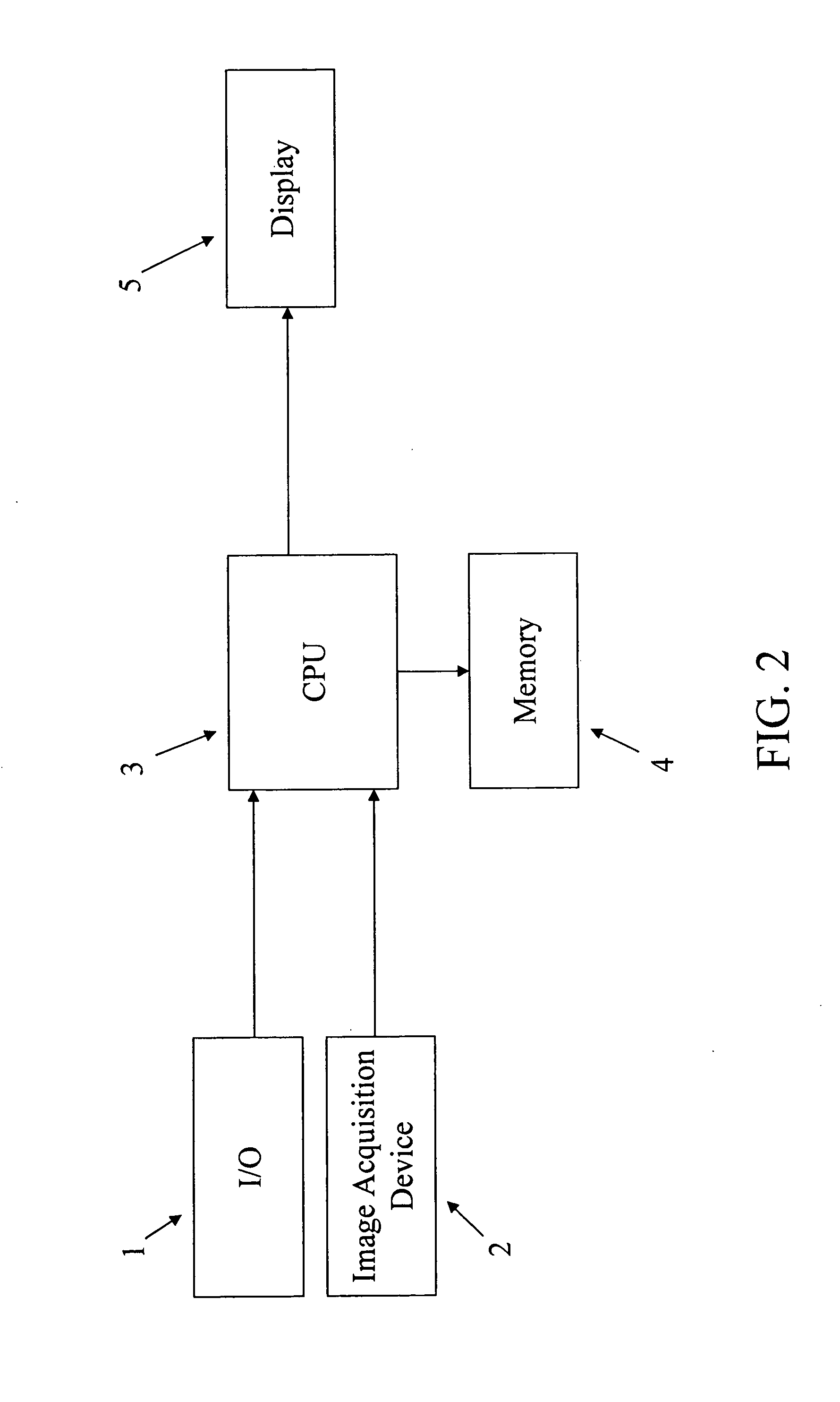
[0029]FIG. 2 illustrates a general purpose system that may be utilized to perform the methods and algorithms disclosed herein. The system shown in FIG. 2 includes an Input / Output (I / O) device 1, an image acquisition device 2, a Central Processing Unit (CPU) 3, a memory 4, and a display 5. This apparatus and particularly the CPU 3 may be specially constructed for the inventive purposes such as a programmed digital signal processor (DSP), an application specific integrated circuit (ASIC), a field programmable gate array (FPGA) or special purpose electronic circuit, or it may comprise a general-purpose computer selectively activated or reconfigu...


PUM


Abstract

This invention solves a problem of registration and improves signal-to-noise ratio (SNR) when using division-by-focal-plane array to produce multiple polarization images. This is achieved by processing a sequence of angular-position-dithered frames to generate a high-definition, Nyquist-sampled, integrated image for each of the polarizations. The integration method transforms individually under-sampled, high-resolution image frames into resultant high-resolution frames that meet the Nyquist sampling criterion. During the resampling transformation, each polarization or waveband is resampled to produce precise registration to the other polarizations, since registration offsets are fixed and defined by the arrangement of the polarized pixels in the focal-plane-array. In the most straight-forward implementation, these offsets would be integer pixel shifts in X and Y.

Description

[0001]This application claims priority to the U.S. Provisional Application No. 60 / 879,326 filed on Jan. 9, 2007 entitled “ENHANCING POLARTIMETER SYSTEMS USING MICRO-POLARIZERS”, which is incorporated herein by reference.FIELD OF INVENTION[0002]The present invention relates to image processing methods, systems, and algorithms that process polarimetric imagery with the purpose of providing high-quality high-resolution polarized imagery that may be used, for example, by subsequent processes to detect and / or classify targets embedded in the imagery. Well known detection and / or classification processes (whether by human observers or by automated methods) may be applied with the inventive image processing.BACKGROUND[0003]There are numerous challenges that must be addressed to provide accurate detection and classification of possible targets based on imagery data. One such challenge is distinguishing targets from the surrounding / background environment. For example, in infrared imagery, the...

Claims


Application Information

Patent Timeline
IPC IPC(8): G01J4/04
CPCG01J4/04
Inventor MATTOX, BARRY G.TENER, GENE D.
Owner LOCKHEED MARTIN CORP
Learn More