X-ray dose compensation method and X-ray computed tomography apparatus

A dose compensation and X-ray technology, applied in X/γ/cosmic radiation measurement, radiation measurement, computerized tomography scanner, etc., can solve the problems of SNR deterioration, reconstructed image noise increase, severe and other problems, to improve SNR Effect

Inactive Publication Date: 2006-04-12
GE MEDICAL SYST GLOBAL TECH CO LLC
View PDF1 Cites 8 Cited by
  • Summary
  • Abstract
  • Description
  • Claims
  • Application Information

AI Technical Summary

Problems solved by technology

[0004] In X-ray CT equipment using multi-array detectors or X-ray plane detectors or X-ray image intensifiers, when the slice thickness is thinner, the slice thickness of the X-ray dose reference channel is also thinner, and it is necessary to use signal-to-noise The X-ray dose of the detector signal from the thin-slice main detector is compensated for by the detector signal of a poorer X-ray dose reference signal, so the SNR deteriorates more in thinner-slice detector arrangements and noise increases on the reconstructed image. bigger and bigger

Method used


Image

  • X-ray dose compensation method and X-ray computed tomography apparatus
  • X-ray dose compensation method and X-ray computed tomography apparatus
  • X-ray dose compensation method and X-ray computed tomography apparatus

Examples


no. 1 example

[0038] Figure 4 A flowchart representing an overview of the operation of the X-ray CT apparatus 100 according to the first embodiment is shown.

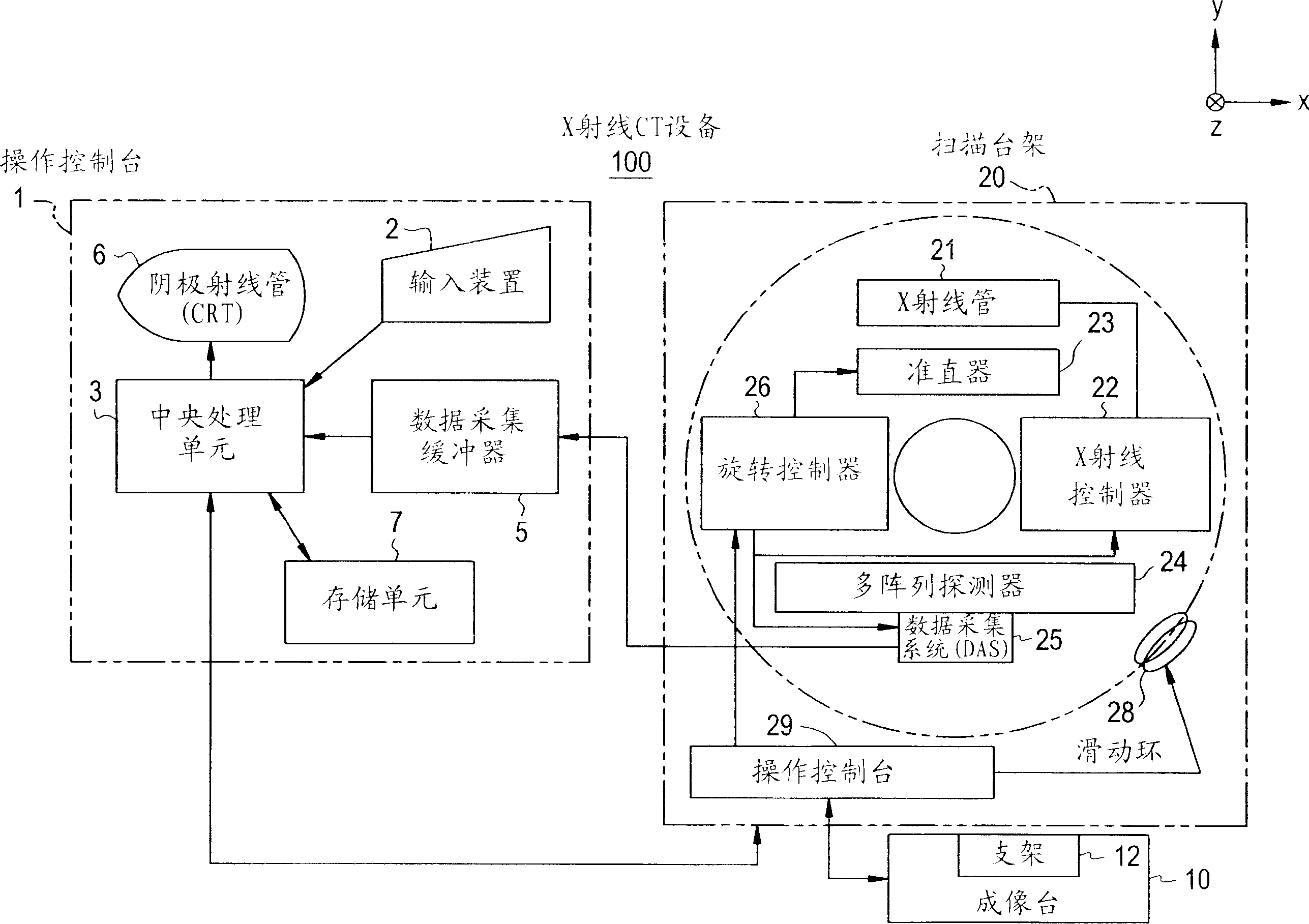
[0039] In step S1, when the X-ray tube 21 and the multi-array detector 24 rotate around the object to be imaged and simultaneously linearly translate the support 12, projection data D0(z, view, j, i) will be collected, where z is the linear translation position, view is the viewing angle, j is the number of detector rows, and i is the number of channels. For helical scans, data acquisition is performed in this manner. For conventional scans (axis scans) or cine scans, data acquisition is performed without moving the carriage 12 horizontally.

[0040] In step S2, the projection data D 0(z, view, j, i) is performed as follows Figure 5 Preprocessing shown (offset correction, algorithm correction, X-ray dose correction, sensitivity correction).

[0041] In step S3, the projection data D0(z, view, j, i) preprocessed according to the...

no. 2 example

[0072] Figure 11 A schematic block diagram of the parts of the device involved in X-ray dose compensation is shown. Such as Figure 11 As shown, the device comprises an X-ray dose signal selector unit 602 . The X-ray dose signal selector unit 602 can be derived from the capabilities of the central processing unit 3 .

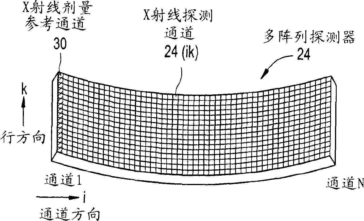
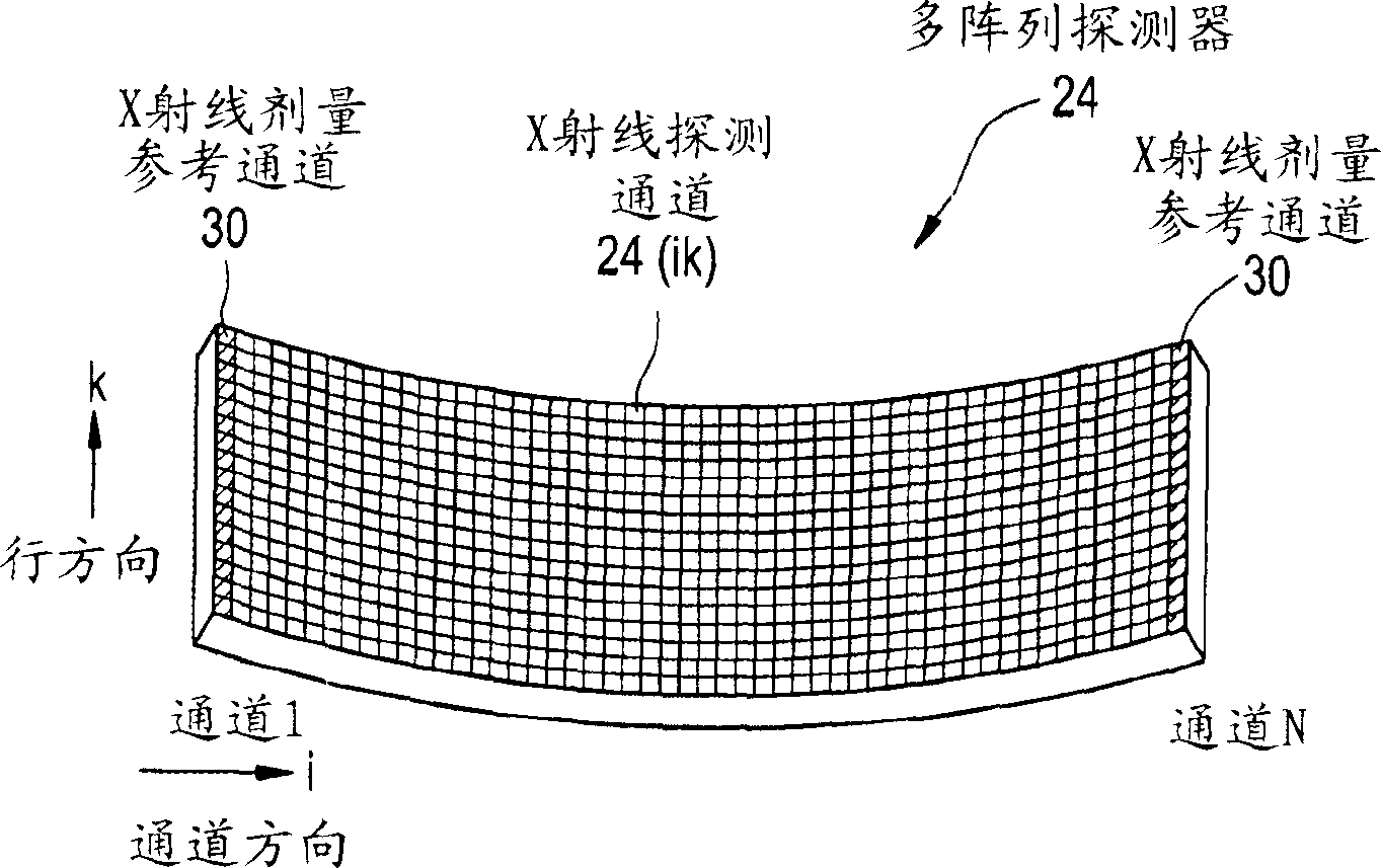
[0073] A series of data D1 , D2 , D3 and Dkm representing the X-ray dose are input to the X-ray dose signal selector unit 602 . The data D1 represents the X-ray dose detected by the left-hand channel of the X-ray dose reference channel 30 . The data D2 represents the X-ray dose detected by the right-hand channel in the X-ray dose reference channel 30 . The data D3 represents the X-ray dose detected by the X-ray detector side channel near the left-hand side or the right-hand side of the X-ray dose reference channel 30 . The data Dkm represents X-ray dose data indicating X-ray tube current or tube voltage information obtained from the X-ray controller 22 of ...


PUM


Abstract

The present invention provides an X-ray dose compensation method for X-ray dose compensation of the detector signals from a multiple array detector with improved SNR, used for the detector signal detected by using the multiple array detector in which a plurality of X-ray detector channels placed in one dimensional array in the channel direction is stacked in a plurality of rows in the row direction to form X-ray detector channels of two dimensional matrix. A plurality of specific X-ray detector channels in the multiple array detector or X-ray planar detector or X-ray image intensifier are used as the X-ray dose reference channels for the X-ray dose compensation by means of signal sum or mean of detector signals from those X-ray dose reference channels.

Description

technical field [0001] The present invention relates to an X-ray dose compensation method and an X-ray CT (Computer Computed Tomography) that compensates the X-ray dose by using an X-ray detection signal detected by a multi-array detector or an X-ray plane detector or an X-ray image intensifier (I.I.). Tomography) apparatus, more particularly to an X-ray dose compensation method and an X-ray CT apparatus capable of improving the SNR (signal-to-noise ratio) of X-ray tomography in all scanning modes including conventional scanning and helical scanning. The multi-array detector here includes multiple lines of multiple X-ray detection channels arranged one-dimensionally along the channel direction. Background technique [0002] An X-ray CT device using a multi-array detector usually contains an X-ray dose detection channel, that is, an X-ray dose reference channel in each row, so that the reference channel of each row independently compensates the X-ray dose of the main detector...

Claims


Application Information

Patent Timeline
IPC IPC(8): A61B6/03
CPCA61B6/032G01T1/2985G01T1/166A61B6/03
Inventor 西出明彦贯井正健
Owner GE MEDICAL SYST GLOBAL TECH CO LLC
Why Eureka
Try Eureka