
Wellhead seal assembly

a technology of seal assembly and wellhead, which is applied in the direction of sealing/packing, mechanical equipment, borehole/well accessories, etc., can solve the problems of sealing leakage and sealing leakag

Active Publication Date: 2010-06-17
VETCO GRAY
View PDF13 Cites 56 Cited by
  • Summary
  • Abstract
  • Description
  • Claims
  • Application Information

AI Technical Summary

Problems solved by technology

A reduction in axial force on the energizing ring results in a reduction in the radial inward and outward forces on the inner and outer walls of the seal ring, which may cause the seal to leak.
A loss of radial loading between the seal and its mating surfaces due to thermal transients may also cause the seal to leak.

Method used


Image

  • Wellhead seal assembly
  • Wellhead seal assembly
  • Wellhead seal assembly

Examples


Embodiment Construction

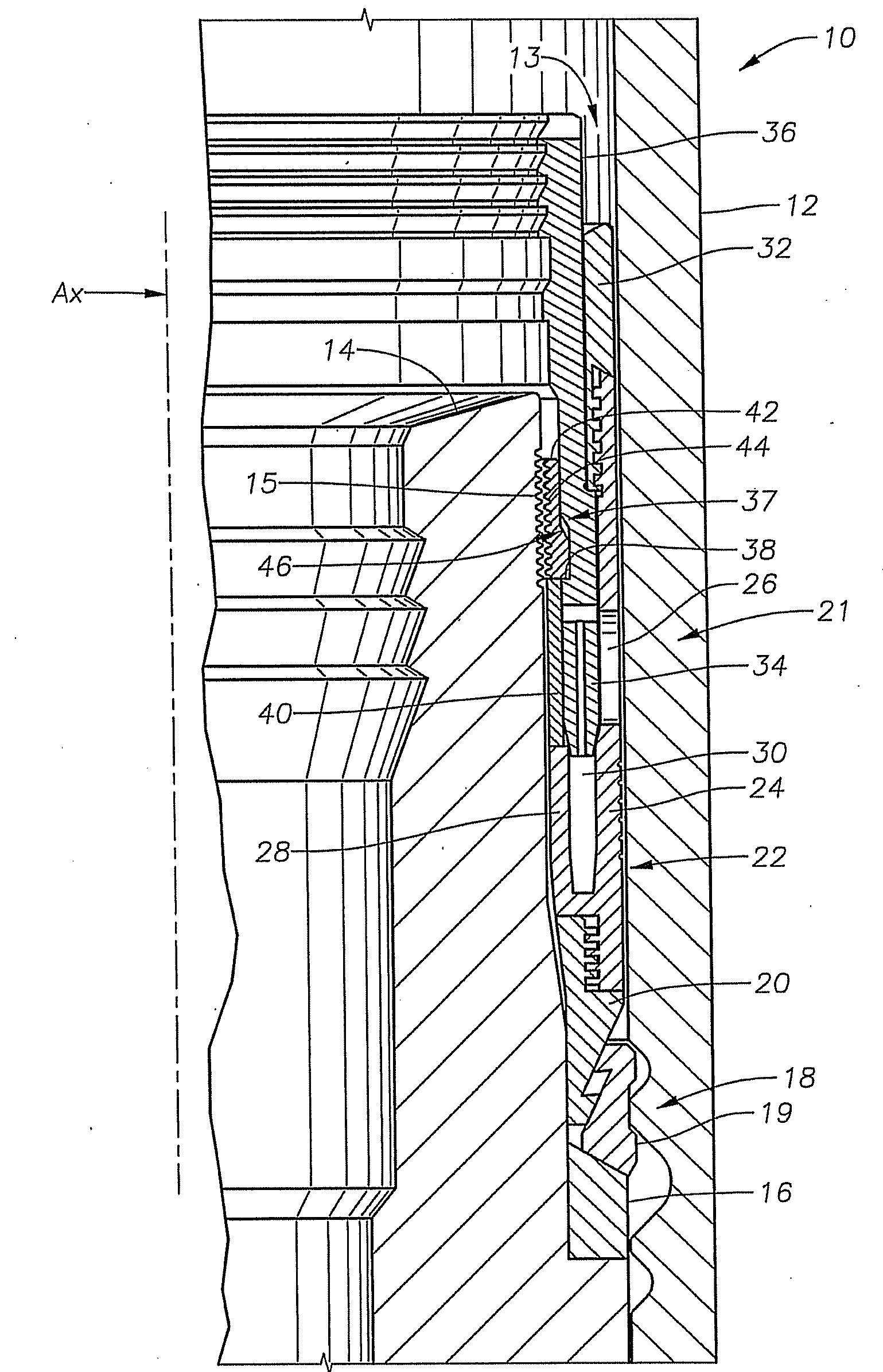
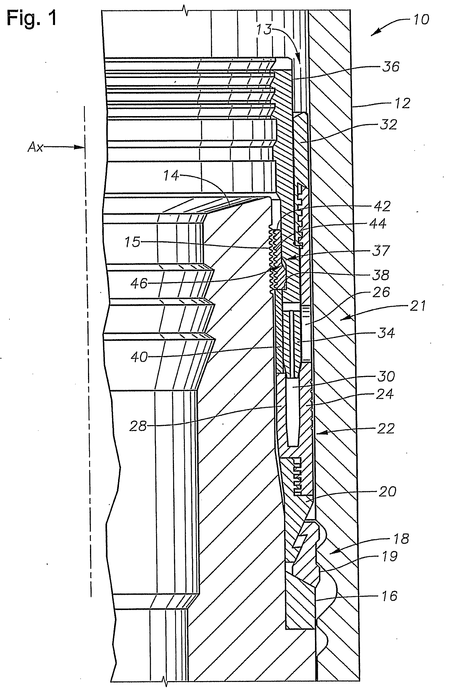
[0014]With reference now to FIG. 1 an example of a wellhead assembly 10 is provided in a side sectional view. In the example of FIG. 1, the wellhead assembly 10 comprises inner and outer wellhead members coaxially disposed and spaced apart thereby forming an annulus there between. The seal assembly is selectively affixed to either of the inner or outer wellhead members to prevent relative movement between the wellhead member and the seal assembly when or if either of the wellhead assemblies axially moves with respect to the other.

[0015]In the specific embodiment of FIG. 1, the wellhead assembly 10 comprises a wellhead housing 12 affixed at an upper end of a wellbore (not shown) and coaxially circumscribing a casing hanger 14. The spaced apart distance between the respective inner and outer circumferences of the casing hanger 14 and wellhead housing 12 form an annulus 13. The casing hanger 14 outer diameter transitions to extend outward into contact with the wellhead housing 12 inner...


PUM


Abstract

A seal assembly for sealing between wellhead members in a wellhead, the assembly may include a seal element and a lockdown member. The seal assembly is attachable to either one of the wellhead members by coupling the lockdown member to a locking surface on the wellhead member. The lockdown member and locking surface may include corresponding profiles for mating engagement thereby preventing relative movement between the wellhead member and seal assembly.

Description

FIELD OF THE INVENTION[0001]This invention relates in general to wellhead assemblies and in particular to a seal for sealing between inner and outer wellhead members.BACKGROUND OF THE INVENTION[0002]Seals are used between inner and outer wellhead tubular members to contain internal well pressure. The inner wellhead member may be a tubing hanger that supports a string of tubing extending into the well for the flow of production fluid. The tubing hanger lands in an outer wellhead member, which may be a wellhead housing, a Christmas tree, or a tubing head. A packoff or seal seals between the tubing hanger and the outer wellhead member. Alternately, the inner wellhead member might be a casing hanger located in a wellhead housing and secured to a string of casing extending into the well. A seal or packoff seals between the casing hanger and the wellhead housing.[0003]A variety of seals of this nature have been employed in the prior art. Prior art seals include elastomeric and partially m...

Claims


Application Information

Patent Timeline
IPC IPC(8): E21B33/03E21B33/04
CPCE21B33/04E21B17/085F16L27/103F16L27/11
Inventor NELSON, JOHN E.
Owner VETCO GRAY
Features
  • Generate Ideas
  • Intellectual Property
  • Life Sciences
  • Materials
  • Tech Scout
  • Unparalleled Data Quality
  • Higher Quality Content
  • 60% Fewer Hallucinations
Learn More