Thermostatic mixing valve

Active Publication Date: 2010-06-17
WATTS REGULATOR
View PDF6 Cites 16 Cited by
  • Summary
  • Abstract
  • Description
  • Claims
  • Application Information

AI Technical Summary

Problems solved by technology

Consequently, when there is an undesirable rise in the temperature of the mixed fluid the thermal motor expands to cause the valve member to reduce the hot flow via the hot inlet port and increase the cold flow via the cold inlet port.

Method used


Image

  • Thermostatic mixing valve
  • Thermostatic mixing valve
  • Thermostatic mixing valve

Examples


Embodiment Construction

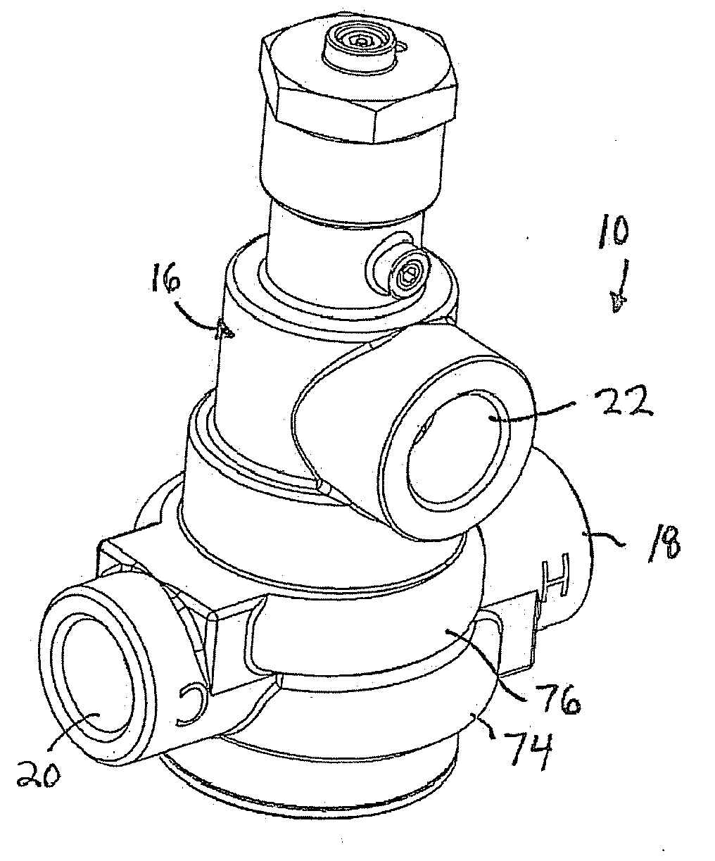
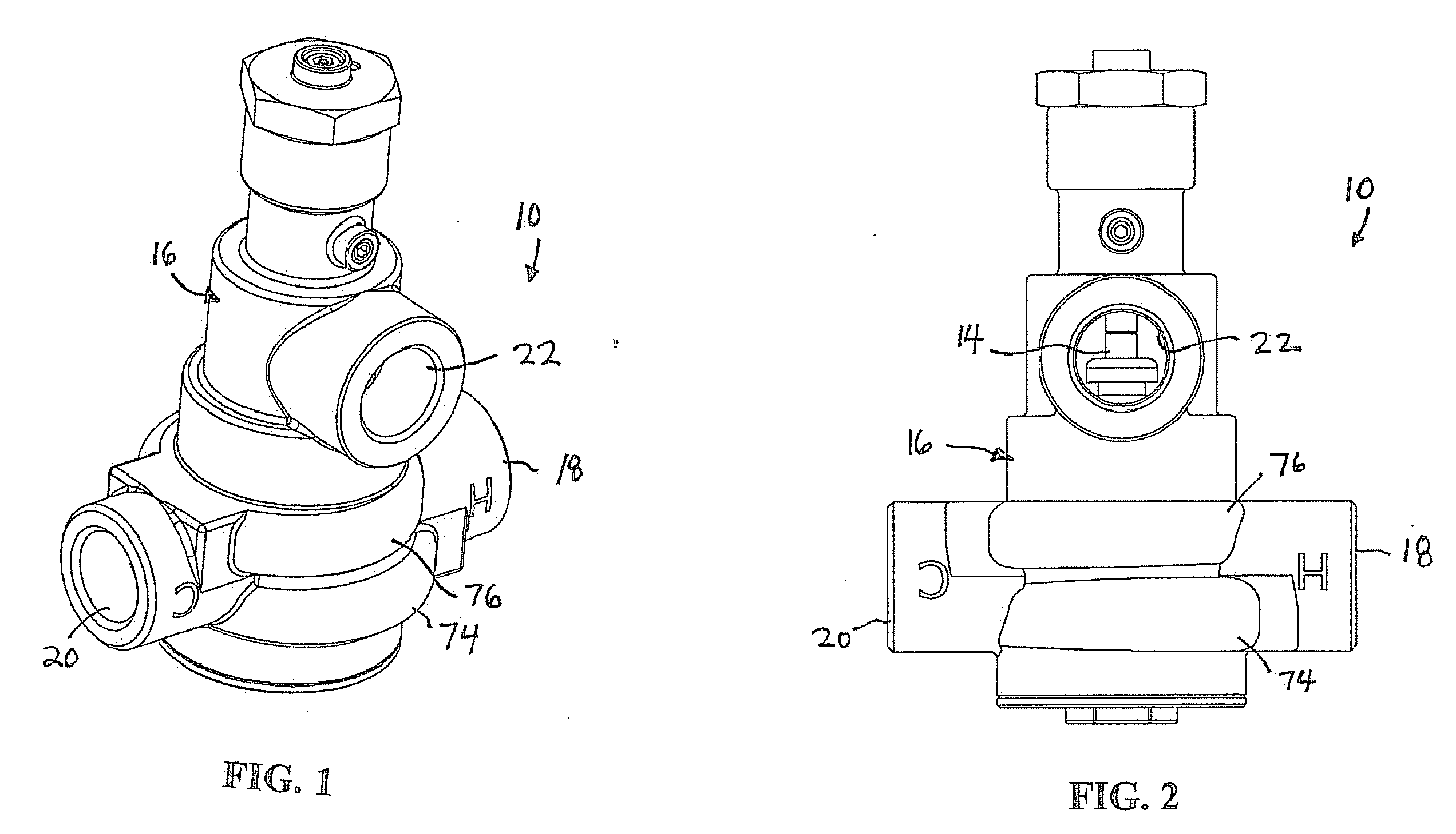
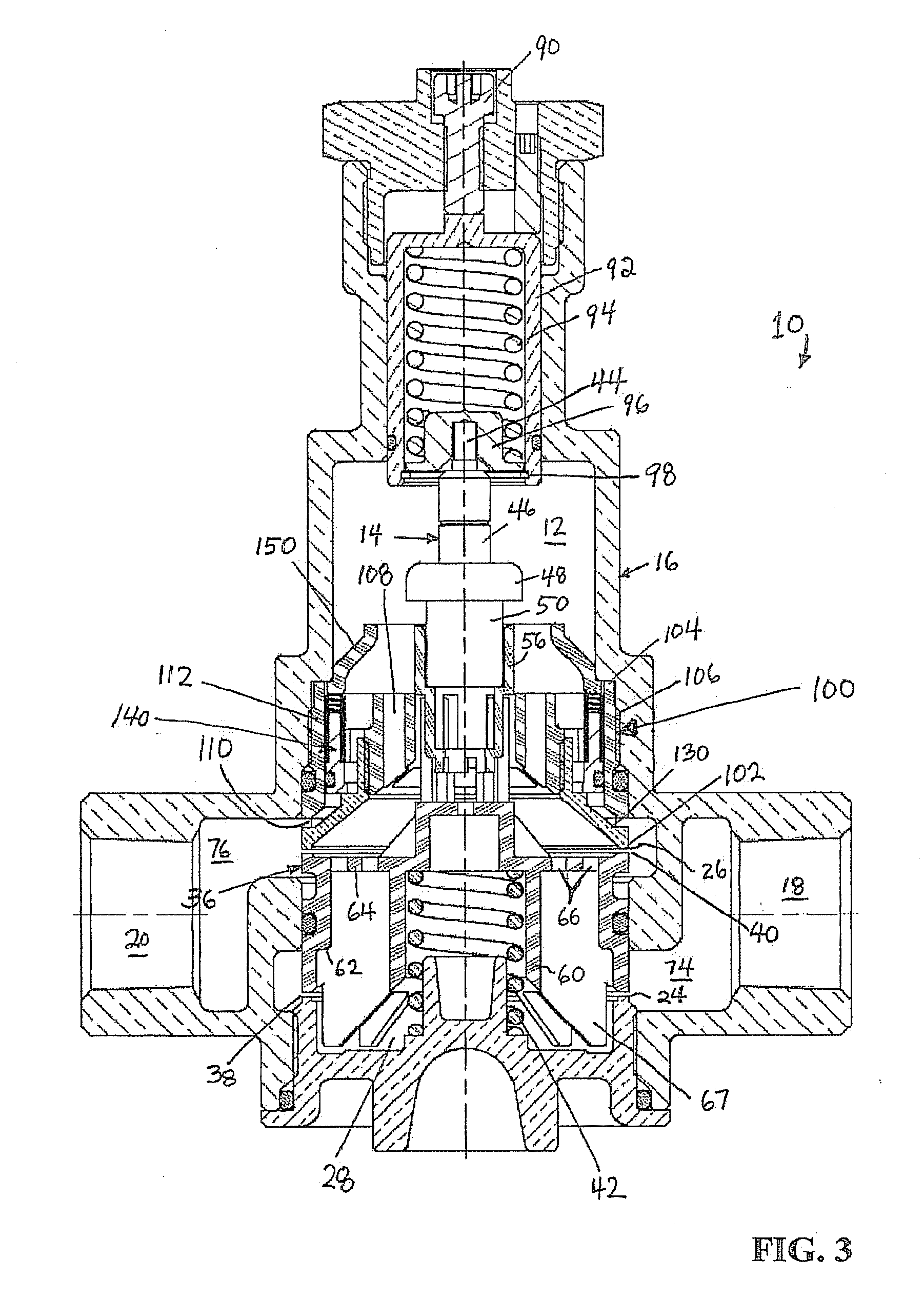
[0028]Referring to FIGS. 1-12, an exemplary embodiment of a new and improved thermostatic mixing valve (TMV) 10 according to the present disclosure is shown. Among other benefits, the new and improved TMV 10 of the present disclosure allows a cold-water bypass upon failure of a hot water supply so that emergency drench shower stations and eyewash stations connected to the TMV remain supplied with water even upon failure of the hot water supply. Without the bypass no water will pass through the TMV since the lack of hot water cause the cold water valve member to be closed.

[0029]The TMV 10 includes a housing 16 having a first inlet 18 for receiving a first fluid and a second inlet 20 for receiving a second fluid, and an outlet 22 for discharging a mixture of the first and the second fluids. In the exemplary embodiment shown, the first inlet 18 is designed to receive hot water, the second inlet 20 is designed to receive cold water, and tempered water is discharged from the outlet 22.

[0...


PUM


Abstract

A thermostatic mixing valve including a cold water bypass passageway controlled by a pressure-operated check valve that opens upon a failure of a hot water supply to the valve. The valve is particularly for use with safety devices, such as eyewash and drench shower stations, and allows the continued delivery of cold water upon a failure of a hot water supply. The lack of hot water causes a cold water valve opening to be closed by a thermal motor, which retracts upon the lack of hot water, yet the bypass passageway is adapted to allow cold water to bypass the thermal motor-controlled cold water valve opening and be directed to the outlet of the valve.

Description

CROSS-REFERENCE TO RELATED APPLICATION[0001]This application claims priority to U.S. Provisional Patent Application No. 61 / 192,051, filed Sep. 15, 2008, which is incorporated herein by reference.TECHNICAL FIELD OF THE DISCLOSURE [0002]The present disclosure generally relates to fluid control valves and, more particularly, to thermostatic mixing valves that mix hot and cold water supplies to produce tempered water. Even more particularly, the present disclosure relates to a thermostatic mixing valve adapted to allow a cold water bypass upon failure of the hot water supply.BACKGROUND OF THE DISCLOSURE [0003]Thermostatic mixing valves (TMVs) are well established and serve to provide a fluid (e.g., water) supply at a desired temperature. TMVs, also referred to as temperature-activated mixing valves, have a temperature responsive thermostat element, or thermal motor, operatively coupled to a valve member controlling fluid flows through hot and cold inlet ports of the valve. The mixed flu...

Claims


Application Information

Patent Timeline
Patent Type & Authority Applications(United States)
IPC IPC(8): G05D23/00
CPCG05D23/1353
Inventor GONCZE, ZOLTAN
Owner WATTS REGULATOR
Why Eureka
Try Eureka