Switchable imaging polarimeter and method

Active Publication Date: 2010-06-17
RAYTHEON CO
View PDF9 Cites 27 Cited by
  • Summary
  • Abstract
  • Description
  • Claims
  • Application Information

AI Technical Summary

Benefits of technology

[0007]To overcome at least the drawbacks of other polarimeters, the polarimeters described herein is operable in a first mode in which the polarimeter can be used to analyze the polarization of the incoming light, such as for use in hazy or dusty conditions when glare is high. In the first mode the incoming light is polarized to determine/analyze the polarization content and about half of the incoming light is lost. This loss of light may limit the usefulness

Problems solved by technology

This loss of light may limit the usefulness of the polarimeter

Method used


Image

  • Switchable imaging polarimeter and method
  • Switchable imaging polarimeter and method
  • Switchable imaging polarimeter and method

Examples


Example

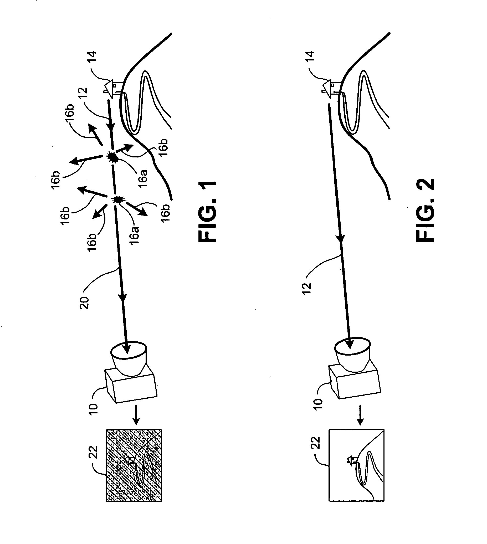
[0038]The polarimeters described herein are selectively operable in a first mode as a polarimeter and a second mode as a standard imager. The two operational modes are illustrated in FIGS. 1 and 2, respectively. Referring initially to FIG. 1, a polarimeter 10 is used to view light 12 from a scene 14 in the first operational state or mode (also referred to as a “polarimeter mode,”“polarizing mode,” or “on state”). As shown in FIG. 1, light 12 from the scene 14 is incident on dust or particles 16a that are suspended in the atmosphere. Some of the light that strikes the particles 16a is scattered, as indicated at 16b. The scattering 16b from the particles 16a may cause incoming light 20 to the polarimeter 10 to be partially polarized. As shown in FIG. 1, the light 12 incident on the particles 16a may be polarized in different directions due to scattering by the particles 16a. Although only two particles 16a are shown, it will be appreciated that the air between the scene 14 and the pol...


PUM


Abstract

A polarimeter and method of polarizing incoming light includes an optical assembly, a first adjustable circular retarder that rotates the polarization content of incoming light, a polarization beam splitter that receives light from the adjustable circular retarder and polarizing the light into a first portion of light having a first polarization and a second portion of light having a second polarization. The first portion of light is directed to a focal plane and the second portion of light is directed to the optical assembly. The optical assembly is switchable between a polarizing mode of operation in which the first portion of light is viewable at the focal plane in absence of the second portion of light and an imaging mode of operation in which the first portion of light and the second portion of light are viewable at the focal plane.

Description

FIELD OF THE INVENTION[0001]The application is in the field of optics, and more particularly to polarimeters.DESCRIPTION OF THE RELATED ART[0002]As light travels through the air it collides with millions of tiny particles. These collisions cause the light to scatter and become partially polarized. Sunlight scattered from these particles make objects and scenes behind the particles more difficult to see. The scattering and glare caused by these collisions increases with the number of particles suspended in the air. For example, the scattering from particles suspended in the air is particularly noticeable in areas having high levels of atmospheric dust, such as dry or arid climates (e.g. deserts) or areas that are frequently hazy from smog or other materials suspended in the air (e.g., cities or densely populated regions).[0003]A polarimeter can be used to analyze the polarization content of the light and filter out light scattered by airborne particles using image processing function...

Claims


Application Information

Patent Timeline
IPC IPC(8): G01J4/04
CPCG01J4/00G02B27/286G01J4/04
Inventor FEST, ERIC C.
Owner RAYTHEON CO
Why Eureka
Try Eureka