Magnetic Drive System and Method

Active Publication Date: 2014-11-13
GARDNER JAMES JOSEPH
View PDF2 Cites 10 Cited by
  • Summary
  • Abstract
  • Description
  • Claims
  • Application Information

AI Technical Summary

Benefits of technology

[0017]Magnetic forces are concentrated at the poles, opposite in polarity, located on opposite ends of the magnet, and not continuous. The lack of continuous magnetic forces greatly limits the usefulness of magnetism. Currently, there is no common practice of efficiently combini

Problems solved by technology

The lack of continuous magnetic forces greatly limits the usefulness of magnetism.
Currently, there is no

Method used


Image

  • Magnetic Drive System and Method
  • Magnetic Drive System and Method
  • Magnetic Drive System and Method

Examples


Example

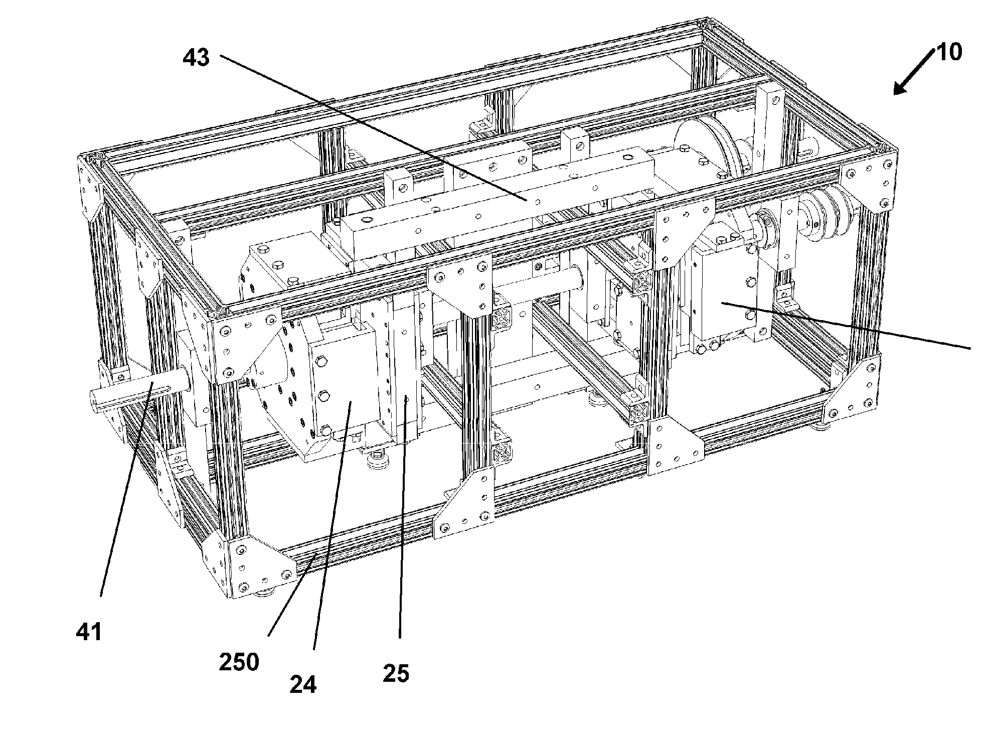
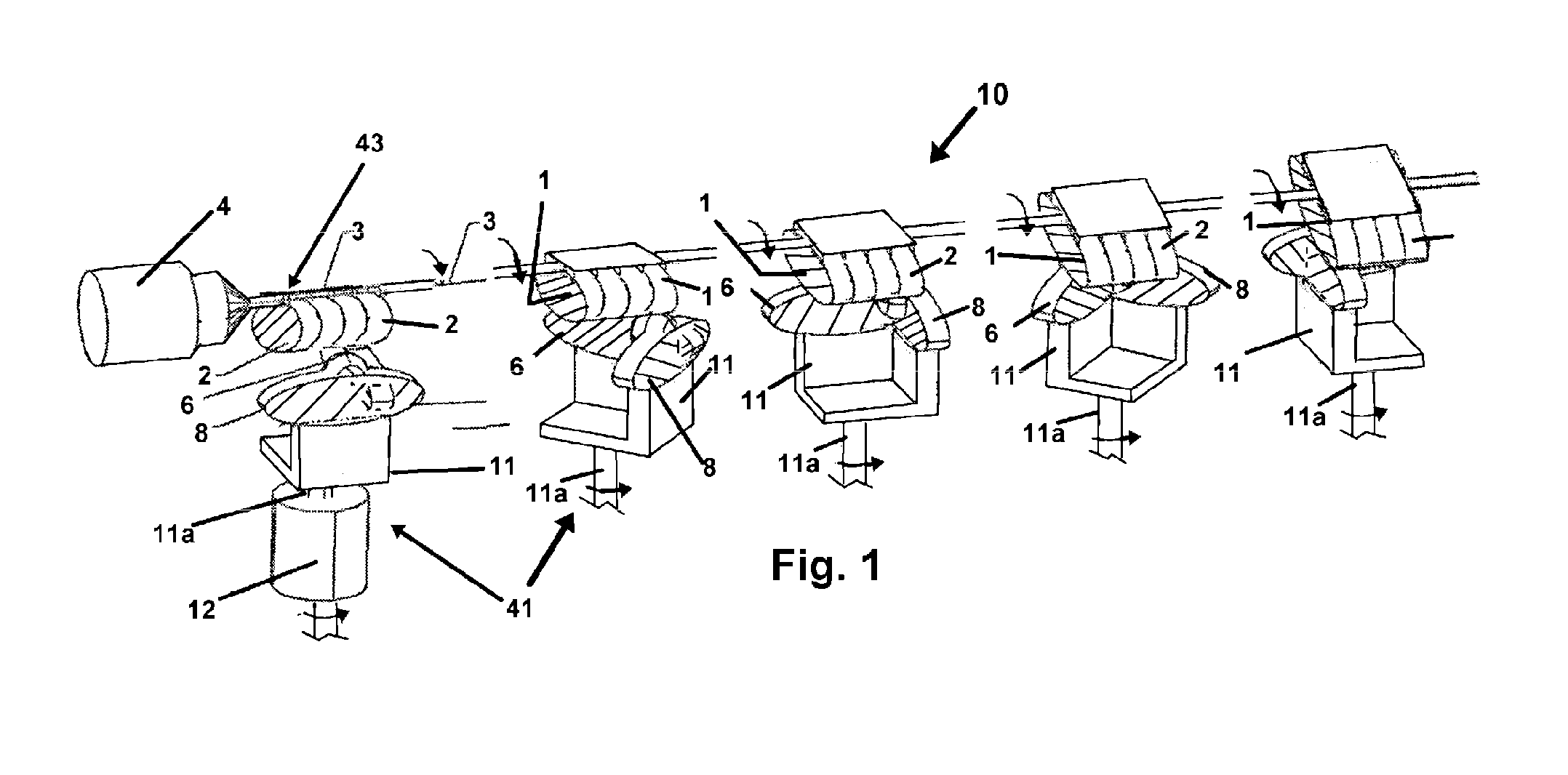
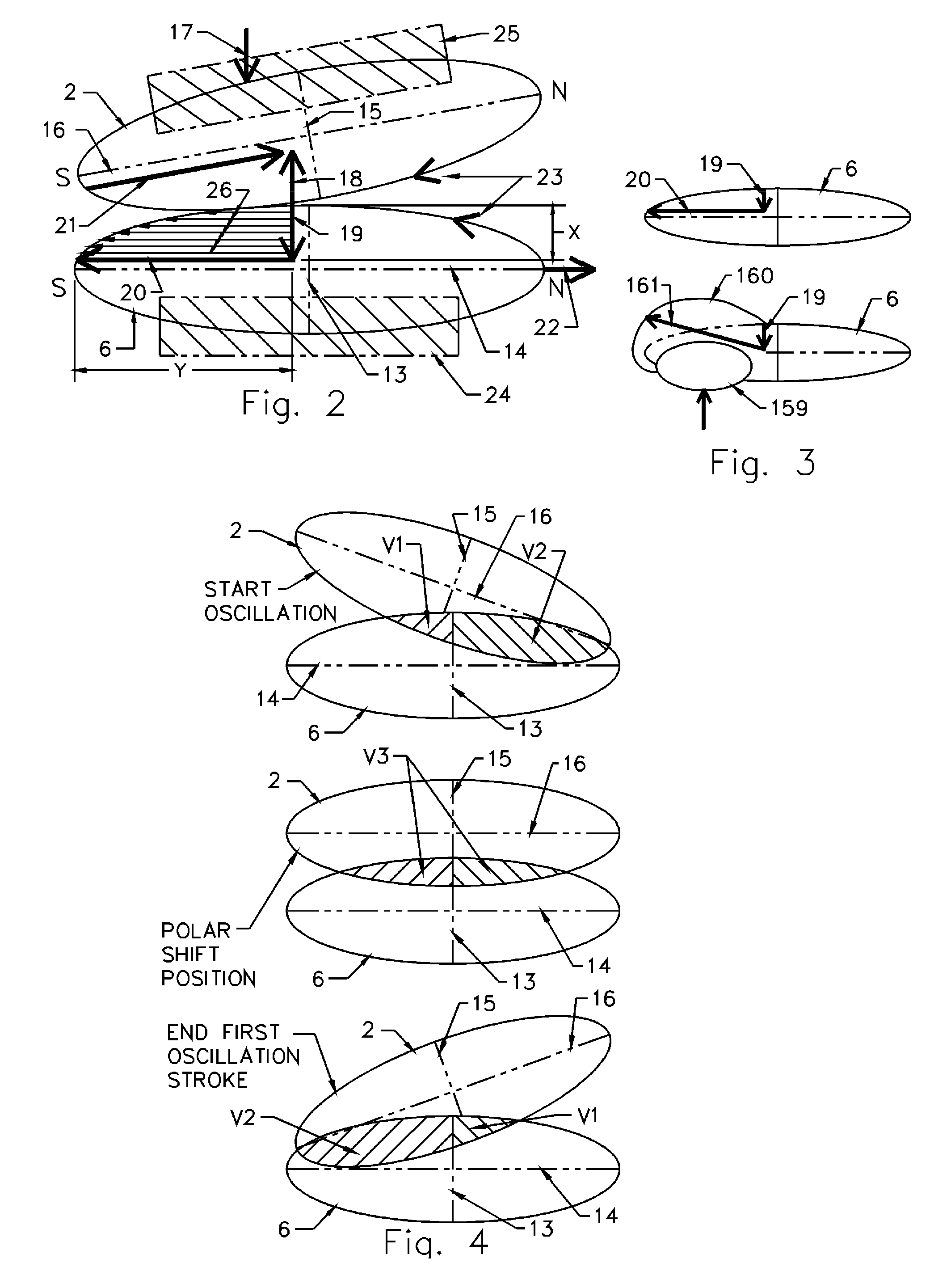
[0045]Referring now to the drawings of FIGS. 1-22 which depict a number of preferred modes of the device 10 and method herein to achieve and employ a magnetic coupling, but which in no manner should be considered limiting. There can be seen in FIG. 1, and related drawings, one exemplary mode of the disclosed method and device 10 herein, wherein there is included at least one oscillation assembly 43, and one rotation assembly 41, wherein each have respective magnetic components that provide magnetic fields whereby the assemblies are engaged for operation. As depicted the ellipsoidal-like fields each have a minor axis, a major axis, and poles located at the extremities of the major axis. Equilibrium is centered between the poles. Each magnetic field has unbalanced regions in either direction from equilibrium that define polar domains that are each dominated by the pole closest to the region.

[0046]In operation, the magnetic fields of the rotation assembly 41 are operationally shaped an...


PUM


Abstract

A magnetic coupling device for communicating continuous rotational or linear motion through a magnetic coupling of magnetic forces communicated from magnets operatively positioned on an oscillation assembly and a rotation assembly in positions sufficiently proximate to form the magnetic coupling. Employed to communicate an output force in a rotational direction from an input linear force communicated from a powered oscillation assembly, the magnetic force of the magnet communicating the force compresses the volume of ellipsoidal-like magnetic fields of the coupling alternately in unlike polar domains, to induce a smooth, blended polar continuity and communicate a continuous 360 degree rotational force to a rotation assembly operatively engaged with the magnetic coupling. The input force may be reversed to induce a continuous linear motion of a reciprocating assembly.

Description

[0001]This application claims priority to U.S. Provisional Patent Application Ser. No. 61 / 822,714 filed on May 13, 2013, and incorporated herein in its entirety by this reference thereto.BACKGROUND OF THE INVENTION[0002]1. Field of the Invention[0003]The disclosed device relates to drive systems for communicating power which is communicated in a first direction to an output in a second direction. More particularly, it relates to a magnetic coupling system for converting power communicated in a first direction such as reciprocating along an axis, to a second direction such as circular. The communication of such force from the power between the two directional systems is provided through such magnetic coupling and without mechanical contact therebetween.[0004]2. Prior Art[0005]Communication of power to perform work frequently involves a change in direction of the communicated power to provide the force in a direction employable for a particular use. For instance, reciprocating motion,...

Claims


Application Information

Patent Timeline
IPC IPC(8): H02K49/10
CPCH02K49/102
Inventor GARDNER, JAMES JOSEPH
Owner GARDNER JAMES JOSEPH
Why Eureka
Try Eureka