Battery holding device

a battery holding and battery technology, applied in the direction of cell components, cell component details, electrochemical generators, etc., can solve the problems of unfavorable cooling air flow and unpredetermined outpu

Active Publication Date: 2010-06-17
HONDA MOTOR CO LTD
View PDF5 Cites 57 Cited by
  • Summary
  • Abstract
  • Description
  • Claims
  • Application Information

AI Technical Summary

Problems solved by technology

Therefore, when a vehicle (such as an EV or a HEV) in which a capacitor including a secondary battery is installed is used in a cold region, particularly, during the winter, a predetermined output may not be obtained because a sufficient amount of e...

Method used


Image

  • Battery holding device
  • Battery holding device
  • Battery holding device

Examples


Embodiment Construction

[0024]Embodiments will now be described with reference to the accompanying drawings, wherein like reference numerals designate corresponding or identical elements throughout the various drawings. A battery holding device according to an embodiment of the present invention will hereunder be described with reference to the drawings.

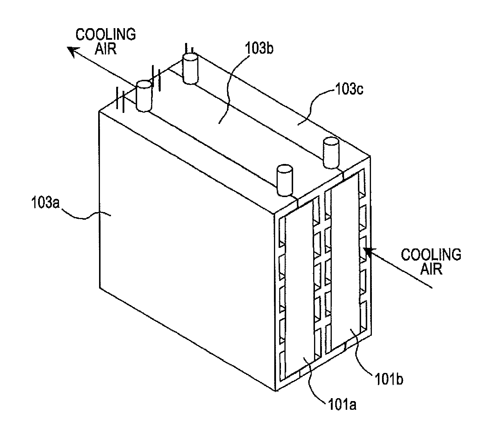
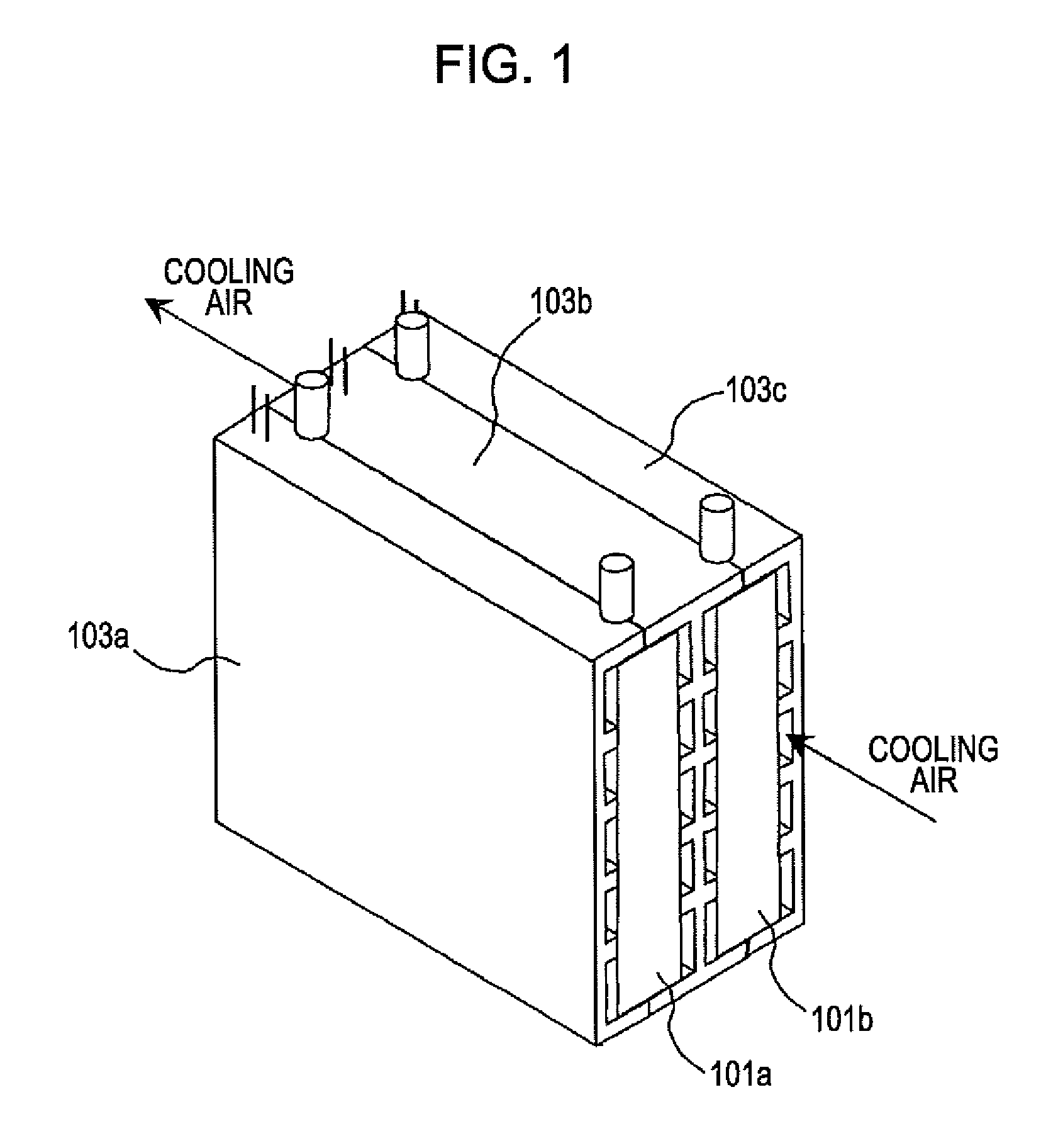
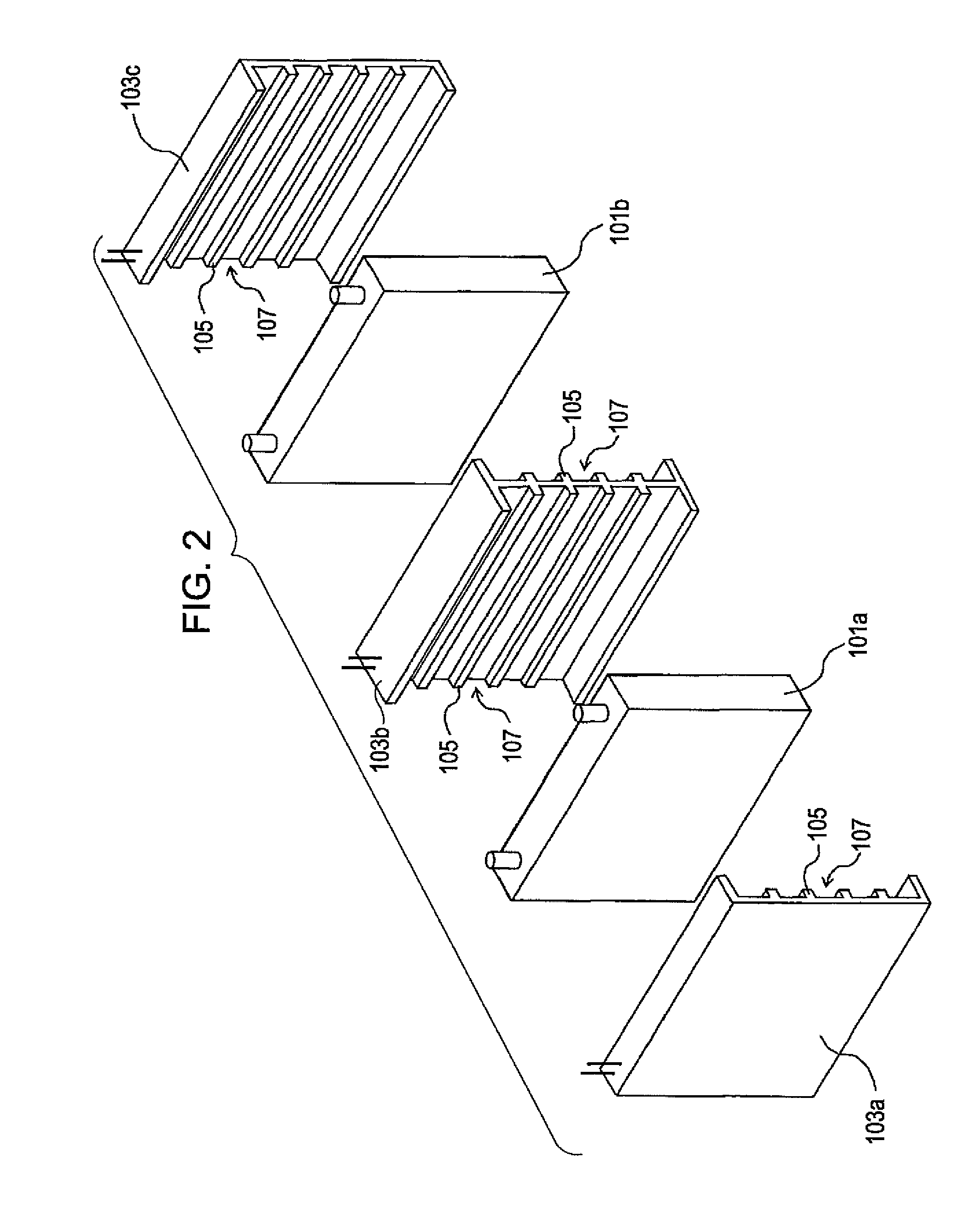
[0025]FIG. 1 is a perspective view of the battery holding device according to the embodiment of the present invention. FIG. 2 is an exploded perspective view of the battery holding device shown in FIG. 1. The battery holding device shown in FIGS. 1 and 2 includes cell holders 103a to 103c integrally formed with a capacitor (including two storage cells 101a and 101b) and holding the storage cells. The cell holders 103a and 103b hold the storage cell 101a, and the cell holders 103b and 103c hold the storage cell 101b. The cell holder 103b is used as a common holding member for the storage cells 101a and 101b, and provides a partition for the storage cell 101a...


PUM


Abstract

A battery holding device is configured to hold a capacitor including at least one storage cell and includes a cell holder and a heater wire. The cell holder is provided at a side surface of at least one storage cell and has a concave-convex surface facing the at least one storage cell. The concave-convex surface has a protrusion contacting the at least one storage cell. At least a portion of the heater wire is embedded in the cell holder.

Description

CROSS-REFERENCE TO RELATED APPLICATIONS[0001]The present application claims priority under 35 U.S.C. §119 to Japanese Patent Application No. 2008-317100, filed Dec. 12, 2008. The contents of this application are incorporated herein by reference in their entirety.BACKGROUND OF THE INVENTION[0002]1. Field of the Invention[0003]The present invention relates to a battery holding device.[0004]2. Discussion of the Background[0005]A capacitor that supplies electrical power to, for example, a motor is installed in a vehicle such as an electric vehicle (EV) or a hybrid electrical vehicle (HEV). A plurality of storage cells that are connected in series are provided in the capacitor. For the storage cells, secondary batteries, such as nickel metal hydride batteries or lithium-ion batteries, are used. The output characteristics of such secondary batteries depend upon temperature, and are reduced when the temperature is low. Therefore, when a vehicle (such as an EV or a HEV) in which a capacitor...

Claims


Application Information

Patent Timeline
IPC IPC(8): H01M2/10H01M10/60H01M10/613H01M10/615H01M10/625H01M10/651H01M10/6557H01M10/6561H01M10/6571H01M50/209H01M50/227
CPCH01M2/1072H01M10/0525H01M10/345H01M10/5004H01M10/5006Y02T10/7011H01M10/5032H01M10/5055H01M10/5059H01M10/5083H01M10/5016H01M10/625H01M10/615H01M10/647H01M10/6571H01M10/6557H01M10/6555H01M10/613Y02E60/10H01M50/209H01M50/227Y02T10/70
Inventor NAGANUMA, ATSUHIRO
Owner HONDA MOTOR CO LTD
Why Eureka
Try Eureka