Apparatus and method for the disassembly and installation of electric motor components

a technology for electric motors and components, applied in the field of machines, can solve the problems of cumbersome and dangerous disassembly and installation of these components, failure of electric motor components or maintenance, and inability to operate compressors and electric motors,

Inactive Publication Date: 2010-06-24
GENERAL ELECTRIC CO
View PDF8 Cites 34 Cited by
  • Summary
  • Abstract
  • Description
  • Claims
  • Application Information

AI Technical Summary

Problems solved by technology

The compressor and electric motors may be operating over extended periods of time and are subject to extreme conditions.
Over time, components of the electric motor may fail or require maintenance.
The disassembly and installation of these components can be cumbersome and dangerous.
In addition, the tool 14 and rotor 18 may have a tendency to sway on the crane 16, which could cause injury.

Method used


Image

  • Apparatus and method for the disassembly and installation of electric motor components
  • Apparatus and method for the disassembly and installation of electric motor components
  • Apparatus and method for the disassembly and installation of electric motor components

Examples


Embodiment Construction

[0026]A more particular description of the invention briefly described above will be rendered by reference to specific embodiments thereof that are illustrated in the appended drawings. Understanding that these drawings depict only typical embodiments of the invention and are not therefore to be considered to be limiting of its scope, the invention will be described and explained. While the invention is described below in reference to electrical motors on air compressors, and may refer to compressors on locomotives and trains the invention is not so limited. The invention may used with other machines that utilize electrical motors including a rotor that may require removal for replacement or maintenance and machines used on other vehicles including marine, off-highway vehicles, on-road vehicles, etc.

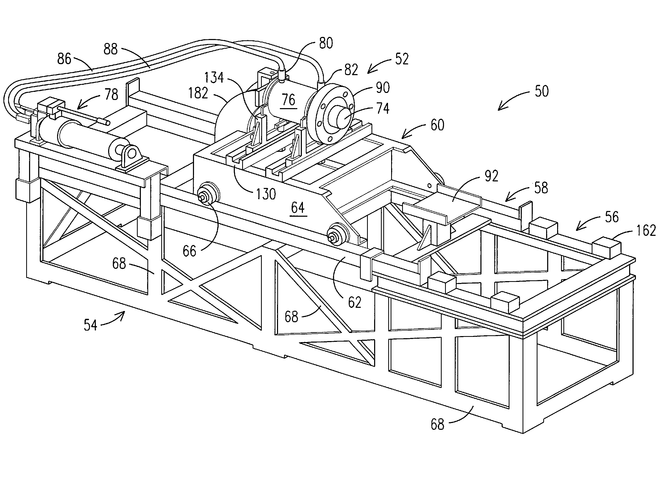
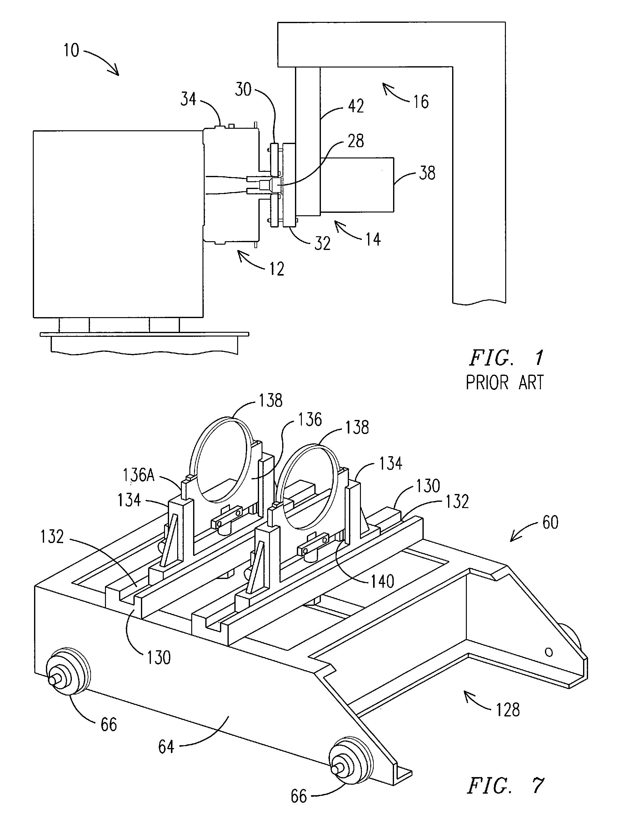
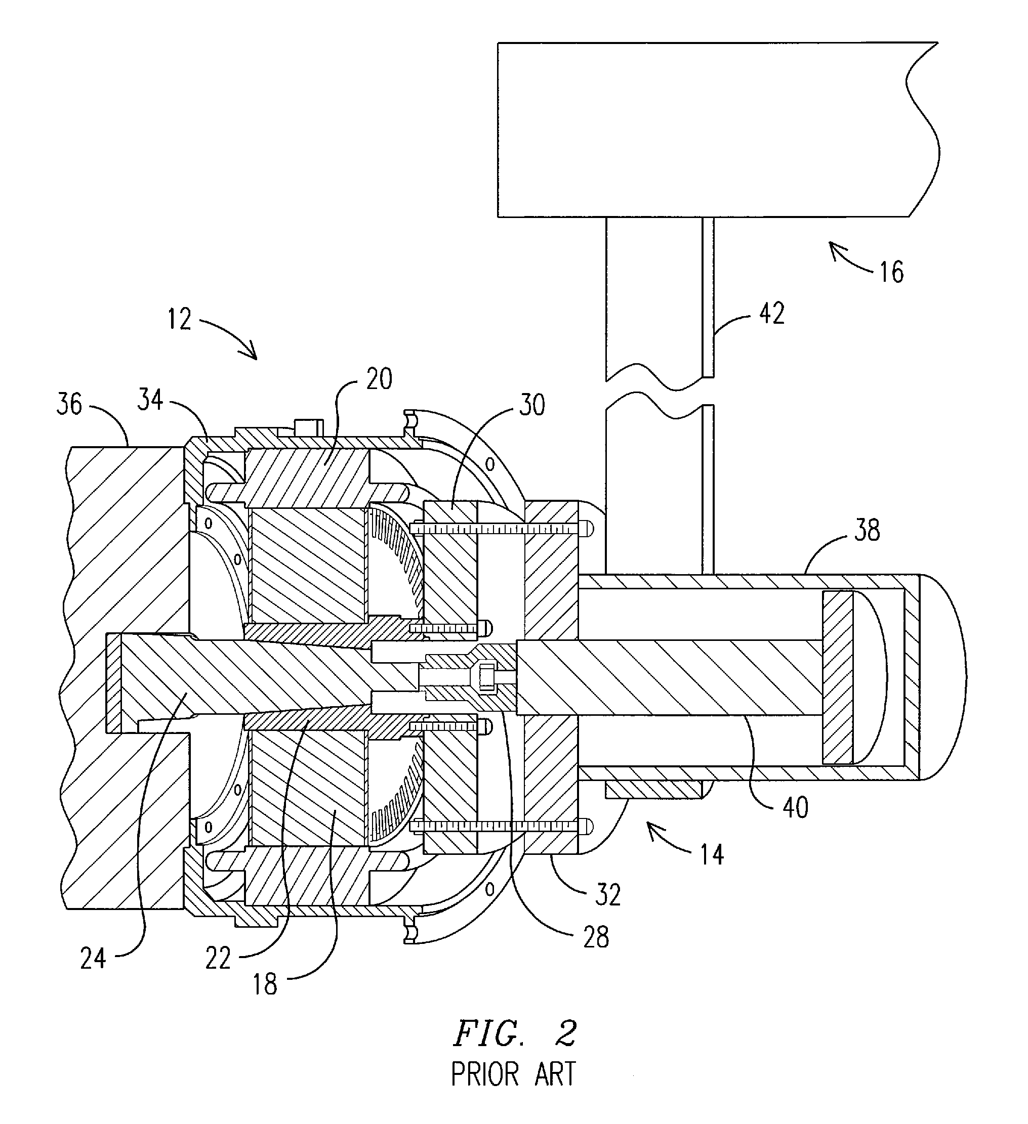
[0027]With respect to FIGS. 4, 5, 6 and 11, there is illustrated an apparatus 50 for removing and installing a rotor 170 (see FIG. 11) from an electrical motor 70 used in operation of a ...


PUM

PropertyMeasurementUnit
rotational forceaaaaaaaaaa
areaaaaaaaaaaa
diameteraaaaaaaaaa

Abstract

An apparatus for removing and installing a rotor in an electric motor that coupled to a shaft of a machine comprises a table having a support area for supporting and mounting the machine and motor. A tool is positioned on the table to move back and forth relative to the machine and motor, and engages the rotor to remove and install the rotor. A flange on the tool is secured to a temporary flange on a rotor sleeve. The tool also includes a piston concentrically aligned with the rotor and shaft to engage the shaft. A driving mechanism is linked to the piston to actuate the piston in a backward or forward direction relative to the machine and motor. The tool housing, responsive to movement of the piston, moves on the table in a direction opposite to the direction of movement of the piston to remove or install the rotor.

Description

BACKGROUND OF THE INVENTION[0001]Embodiments of the invention generally relate to machines, such as air compressor systems, that incorporate electric motors having internal components including a stator and rotor. More specifically, embodiments of the invention relate to the disassembly and installation of components of the electric motor for testing, reconditioning, or replacing such components.[0002]Machines such as air compressors are used on locomotives and include electric motors to power the compressors, which generate and supply compressed air to operating components on the locomotive. The compressor and electric motors may be operating over extended periods of time and are subject to extreme conditions. Over time, components of the electric motor may fail or require maintenance. Accordingly, the components of an electric motor such as the rotor and stator must be removed from the electric motor housing on the compressor in order to replace or recondition the components. For ...

Claims


Application Information

Patent Timeline
Patent Type & Authority Applications(United States)
IPC IPC(8): H02K15/00
CPCH02K15/0006H02K15/16Y10T29/53143Y10T29/53274Y10T29/49012
Inventor PERVAIZ, MUHAMMAD
Owner GENERAL ELECTRIC CO
Why Eureka
Try Eureka