Supersonic compressor

a compressor and supersonic technology, applied in the direction of supersonic fluid pumps, machines/engines, liquid fuel engines, etc., can solve the problems of large complexity, high cost, and limited use of conventional compressor systems, and achieve the effect of improving the efficiency of the compressor system, reducing the cost of operation, and increasing the cost of operation

Active Publication Date: 2010-06-24
NUOVO PIGNONE TECH SRL
View PDF6 Cites 11 Cited by
  • Summary
  • Abstract
  • Description
  • Claims
  • Application Information

AI Technical Summary

Problems solved by technology

Conventional compressor systems, while exceedingly useful, are limited in that the pressure ratio achievable by a single stage of a compressor is relatively low.
However, conventional compressor systems comprising multiple compression stages tend to be large, complex and high cost.

Method used


Image

  • Supersonic compressor
  • Supersonic compressor
  • Supersonic compressor

Examples


Embodiment Construction

[0015]In the following specification and the claims, which follow, reference will be made to a number of terms, which shall be defined to have the following meanings.

[0016]The singular forms “a”, “an”, and “the” include plural referents unless the context clearly dictates otherwise.

[0017]“Optional” or “optionally” means that the subsequently described event or circumstance may or may not occur, and that the description includes instances where the event occurs and instances where it does not.

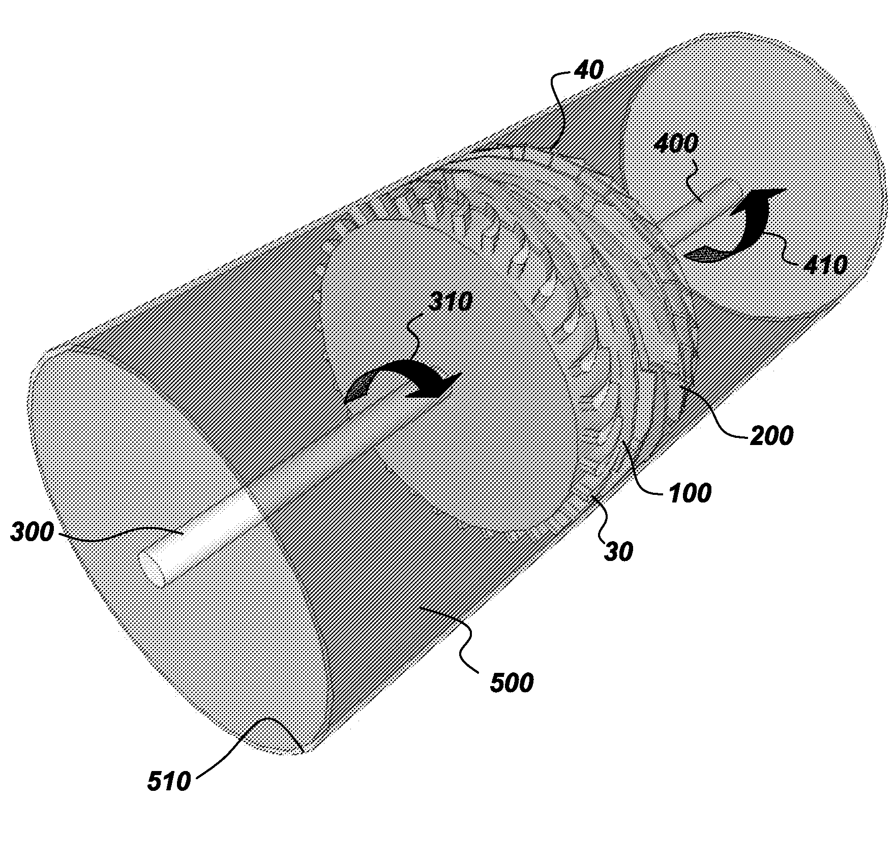
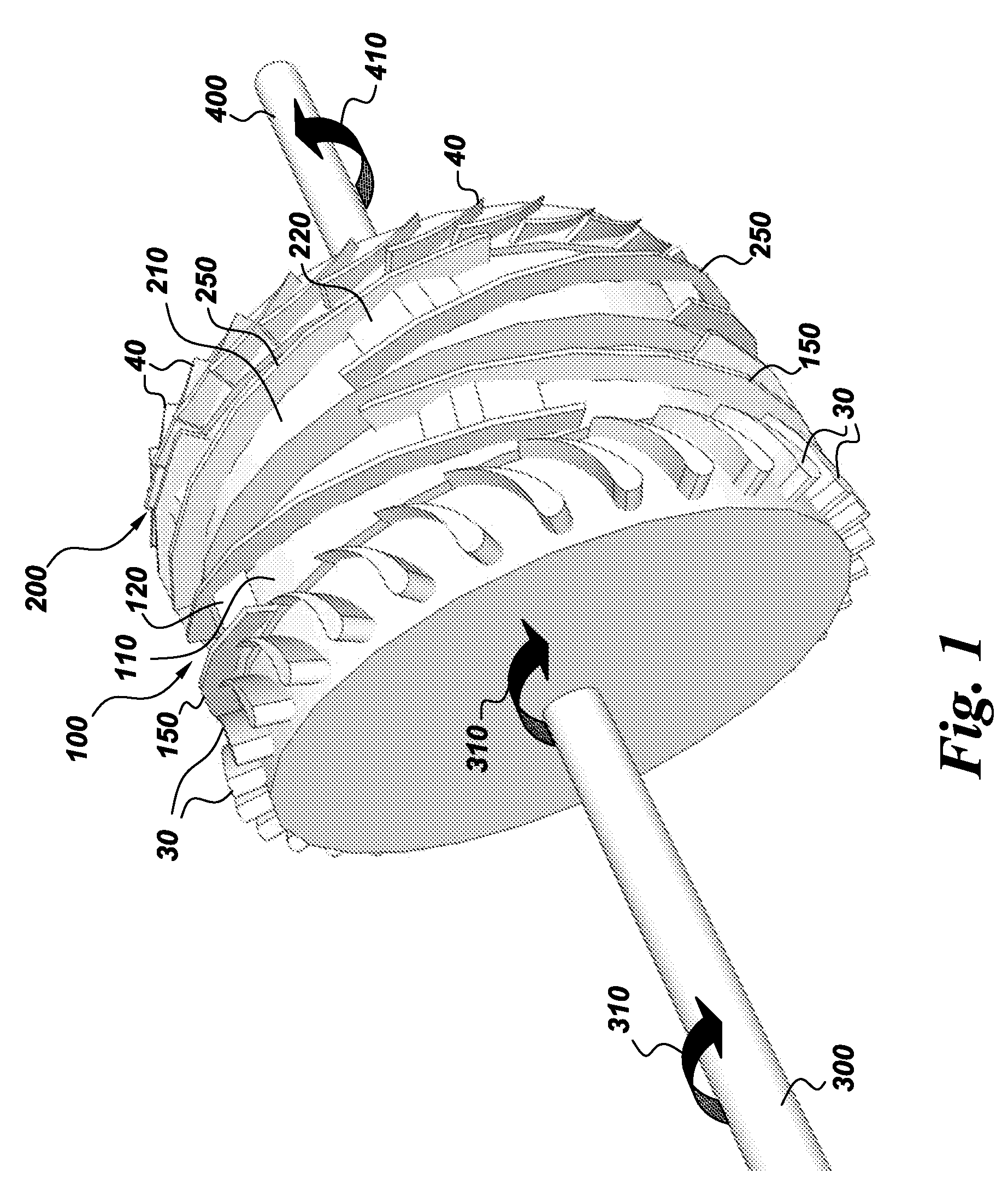
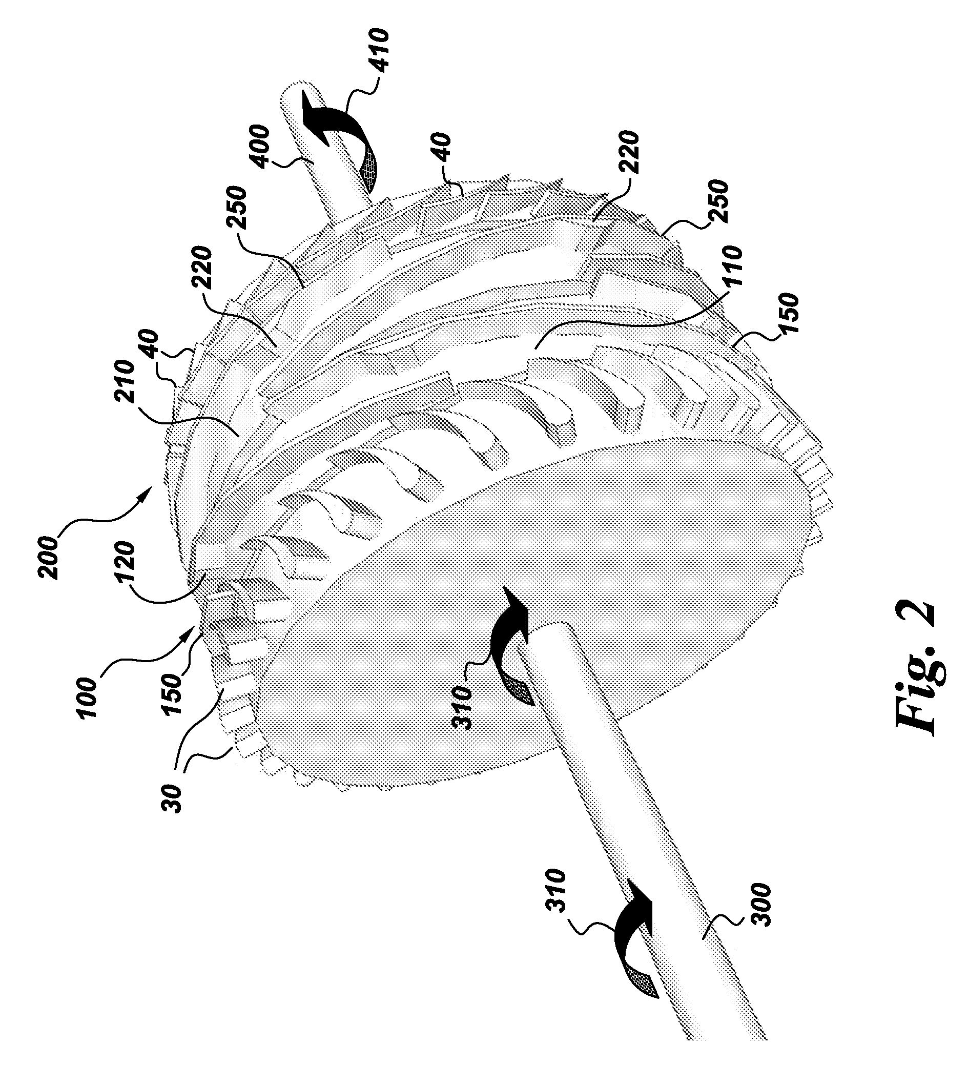
[0018]As used herein, the term “supersonic compressor” refers to a compressor comprising a supersonic compressor rotor.

[0019]Approximating language, as used herein throughout the specification and claims, may be applied to modify any quantitative representation that could permissibly vary without resulting in a change in the basic function to which it is related. Accordingly, a value modified by a term or terms, such as “about” and “substantially”, are not to be limited to the precise value spec...


PUM


Abstract

A novel supersonic compressor is provided by the present invention. In one embodiment, the novel supersonic compressor comprises a fluid inlet, a fluid outlet, and at least two counter rotary supersonic compressor rotors, said supersonic compressor rotors being configured in series such that an output from a first supersonic compressor rotor having a first direction of rotation is directed to a second supersonic compressor rotor configured to counter-rotate with respect to the first supersonic compressor rotor.

Description

BACKGROUND[0001]The present invention relates to compressors and systems comprising compressors. In particular, the present invention relates to supersonic compressors comprising supersonic compressor rotors and systems comprising the same.[0002]Conventional compressor systems are widely used to compress gases and find application in many commonly employed technologies ranging from refrigeration units to jet engines. The basic purpose of a compressor is to transport and compress a gas. To do so, a compressor typically applies mechanical energy to a gas in a low pressure environment and transports the gas to and compresses the gas within a high pressure environment from which the compressed gas can be used to perform work or as the input to a downstream process making use of the high pressure gas. Gas compression technologies are well established and vary from centrifugal machines to mixed flow machines, to axial flow machines. Conventional compressor systems, while exceedingly usefu...

Claims


Application Information

Patent Timeline
Patent Type & Authority Applications(United States)
IPC IPC(8): F04D19/02F04D29/32
CPCF04D21/00F04D17/127F04D19/024F04D29/263F04D29/324F04D29/388
Inventor HOFER, DOUGLAS CARLNAGEL, ZACHARY WILLIAMHOLMES, DAVID GRAHAM
Owner NUOVO PIGNONE TECH SRL
Why Eureka
Try Eureka