Connector

a technology of connecting rods and connectors, applied in the direction of coupling devices, coupling bases/cases, securing/insulating coupling contact members, etc., can solve the problems of high manufacturing cost of connectors b>101/b>, prevent terminal growth, prevent the effect of reducing the cross-section of electrical connectors, and prevent the elastomer seal from receding

Active Publication Date: 2010-06-24
YAZAKI CORP
View PDF13 Cites 27 Cited by
  • Summary
  • Abstract
  • Description
  • Claims
  • Application Information

AI Technical Summary

Benefits of technology

[0017]According to the above illustrative aspect of an exemplary embodiment of the present invention, the elastic seal is supported from its back side by the support member abutting the engagement portion. Thus, the elastic seal is prevented from receding relative to the electrical connector. Therefore, the sealing between the outer periphery of the electrical connector and the inner peripheral wall of the terminal space is secured.
[0018]Also, since the rigidity of the support member is higher than the rigidity of the elastic seal, a space for engagement between the engagement portion and the support member (space for abutment) for preventing the support member from receding relative to the electrical connector by the abutment for the engagement portion may be smaller than a case where only the elastic seal is used. Thereby, the growth in size of the terminal is prevented, and reduction in the cross-section of the electrical connector is prevented causing the amount of the allowable curre

Problems solved by technology

Therefore, the manufacturing of

Method used


Image

  • Connector
  • Connector
  • Connector

Examples


Embodiment Construction

[0027]Below an exemplary embodiment of the present invention is explained with reference to drawings.

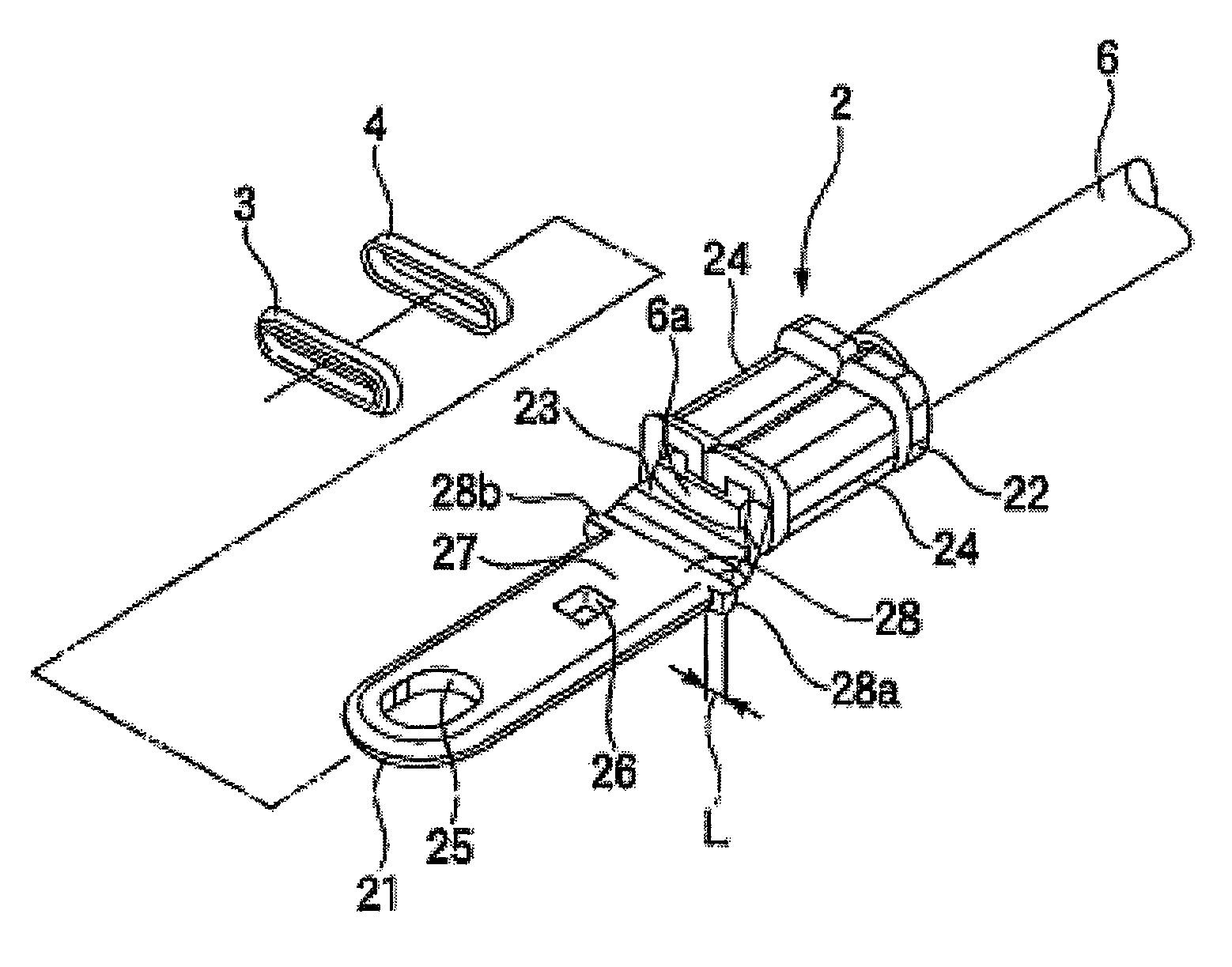
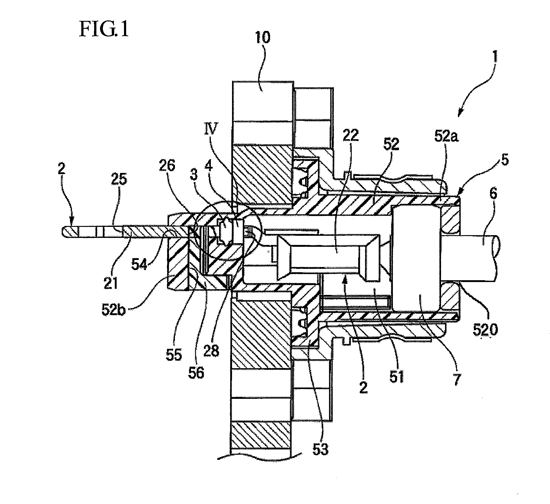
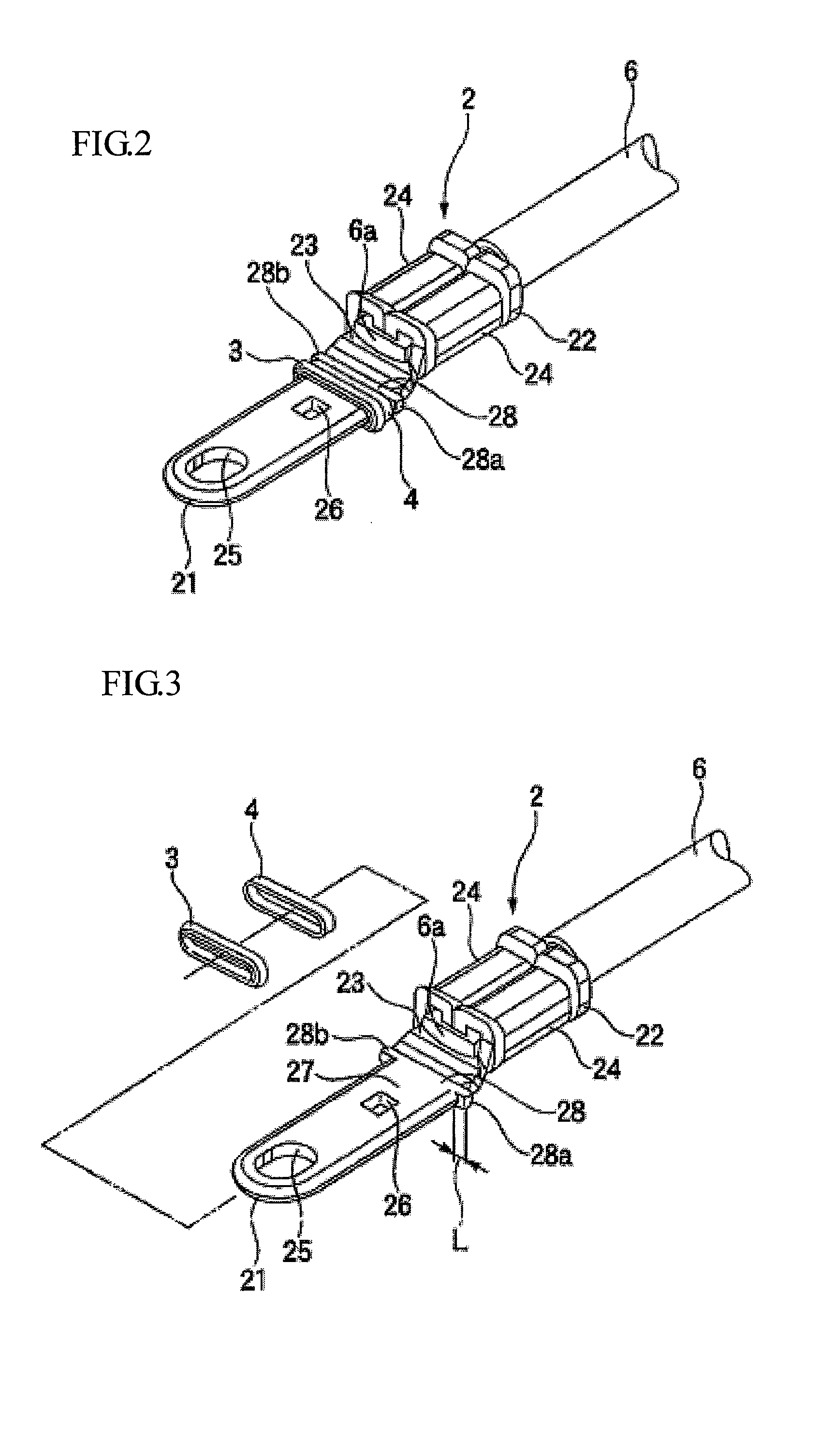
[0028]FIG. 1 is a sectional view of an exemplary embodiment of a connector according to the present invention. FIG. 2 is a perspective view of the exemplary embodiment of the connector shown in FIG. 1. FIG. 3 is an exploded perspective view of a terminal shown in FIG. 2.

[0029]A connector 1 includes a terminal 2 to which a wire 6 is connected, a connector housing having a terminal space 51 into which the terminal 2 is inserted, an elastic seal 3 which is attached to the terminal 2, and a supporting member 4. The connector 1 is attached to a chassis 10 of an apparatus.

[0030]The terminal 2 has an electrical connector 21 to which a counterpart connector is connected, and a wire connector 22 to which the wire 6 is connected (The counter part connector is not shown).

[0031]The connector housing 5 includes a body 52 and a flange 53. The body 52 defines the terminal space 51 in a rectangular ...


PUM


Abstract

A terminal comprising a plate shaped electrical connector including an engagement portion and an equipment portion, a ring shaped support member intimately attached to an outer periphery of the equipment portion and abutting to the engagement portion, and a ring shaped elastic seal intimately attached to the outer periphery of the equipment portion and adjacent to the support member from a side of the support member opposite a side abutting the engagement portion. Also, a connector comprising the terminal and a connector housing including a terminal space into which the terminal is inserted, the terminal space having an inner peripheral wall.

Description

REFERENCE TO RELATED APPLICATION[0001]This application claims priority from Japanese Patent Application No. 2008-328648 filed on Dec. 24, 2008, and the subject matter of which is incorporated herein by reference.TECHNICAL FIELD[0002]The present invention relates to a connector which has a structure to prevent liquid, such as water, oil, or the like, from intruding into a terminal space of a connector housing.BRIEF DESCRIPTION OF RELATED ART[0003]Related art JP-A-2003-109702 describes a connector, which has a structure to prevent liquid, such as water, oil, or the like, from intruding into a terminal space of a connector housing.FIG. 6 shows this related art.[0004]The related connector 101 includes a terminal 123 which has a electrical connector 126 having a rectangular-plane shape, a connector housing 112 which has a terminal space 113 into which the terminal 123 is inserted, and a circular elastic seal 128 which is attached to a periphery of the electrical connector 126 of the term...

Claims


Application Information

Patent Timeline
IPC IPC(8): H01R13/40
CPCH01R13/521H01R13/426
Inventor KATO, HAJIMEMIZUSHIMA, TSUYOSHIOZAKI, YOSHIAKI
Owner YAZAKI CORP
Why Eureka
Try Eureka