
Weight shifting apparatus for an orthopedic sling

a technology for orthopedic slings and sling straps, which is applied in the field of orthopedic sling weight shifting apparatuses, can solve the problems of large localized pressure on the strap of the sling, common and extremely annoying problems of medical products, and significant discomfort of patients, and achieve the effect of transferring the weight and resulting pressur

Active Publication Date: 2010-06-24
WICKSTROM CHRISTOPHER MICHAEL
View PDF7 Cites 5 Cited by
  • Summary
  • Abstract
  • Description
  • Claims
  • Application Information

AI Technical Summary

Benefits of technology

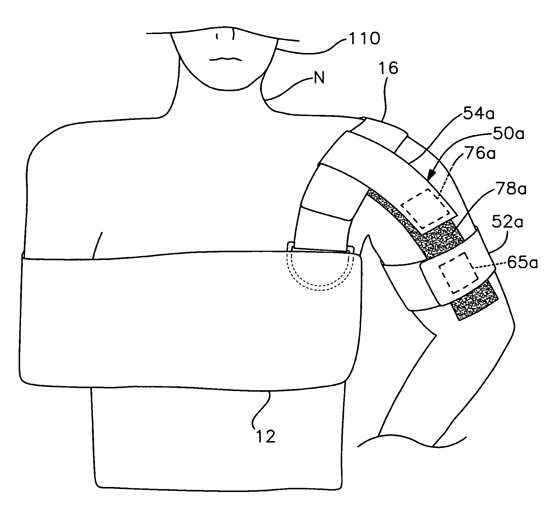
[0006]It is therefore an object of the present invention to provide an apparatus for simply and conveniently transferring the weight and resulting pressure exerted by an orthopedic sling and supported arm from the neck to the well shoulder of the wearer.
[0007]It is a further object of this invention to provide a weight shifting constraint apparatus for an orthopedic sling that is extremely comfortable to wear and which does not interfere with movement of the wearer's well arm or torso.
[0008]It is a further object of this invention to provide a weight shifting constraint apparatus for an orthopedic sling that is quick, easy and convenient to put on and remove as needed.

Problems solved by technology

Unfortunately, this type of medical product exhibits a common and extremely annoying problem.
The weight of the supported arm, which is often compounded by a cast, bandages, etc., typically causes the strap of the sling to exert a large amount of localized pressure against the wearer's neck and, in particular, the trapezius muscle.
This can cause the patient significant discomfort and result in neck pulls, strains and fatigue, as well as unwanted pressure on the carotid artery.
Although such pads have provided some relief, they are still not satisfactorily addressing the problem.
However, these products are unduly cumbersome and quite uncomfortable to wear.
They also tend to greatly restrict the patient's ability to move his or her torso.
That product is not adaptable for use with the vast majority of standard orthopedic slings already on the market.

Method used


Image

  • Weight shifting apparatus for an orthopedic sling
  • Weight shifting apparatus for an orthopedic sling
  • Weight shifting apparatus for an orthopedic sling

Examples


Embodiment Construction

[0019]Other objects, features and advantages will occur from the following description of a preferred embodiment and the accompanying drawings, in which:

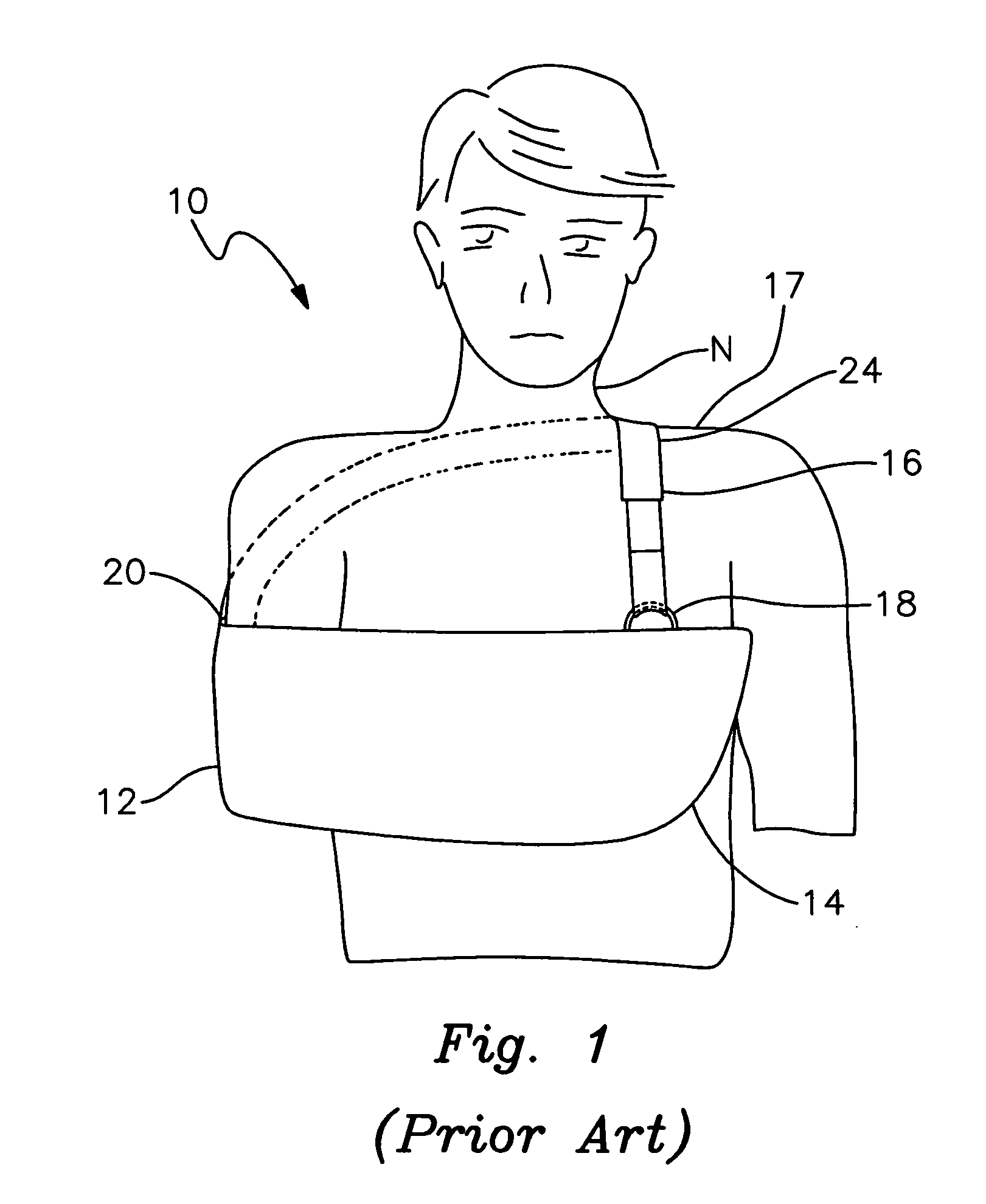
[0020]FIG. 1 is a front elevational view of a patient wearing a conventional orthopedic sling in accordance with the prior art;

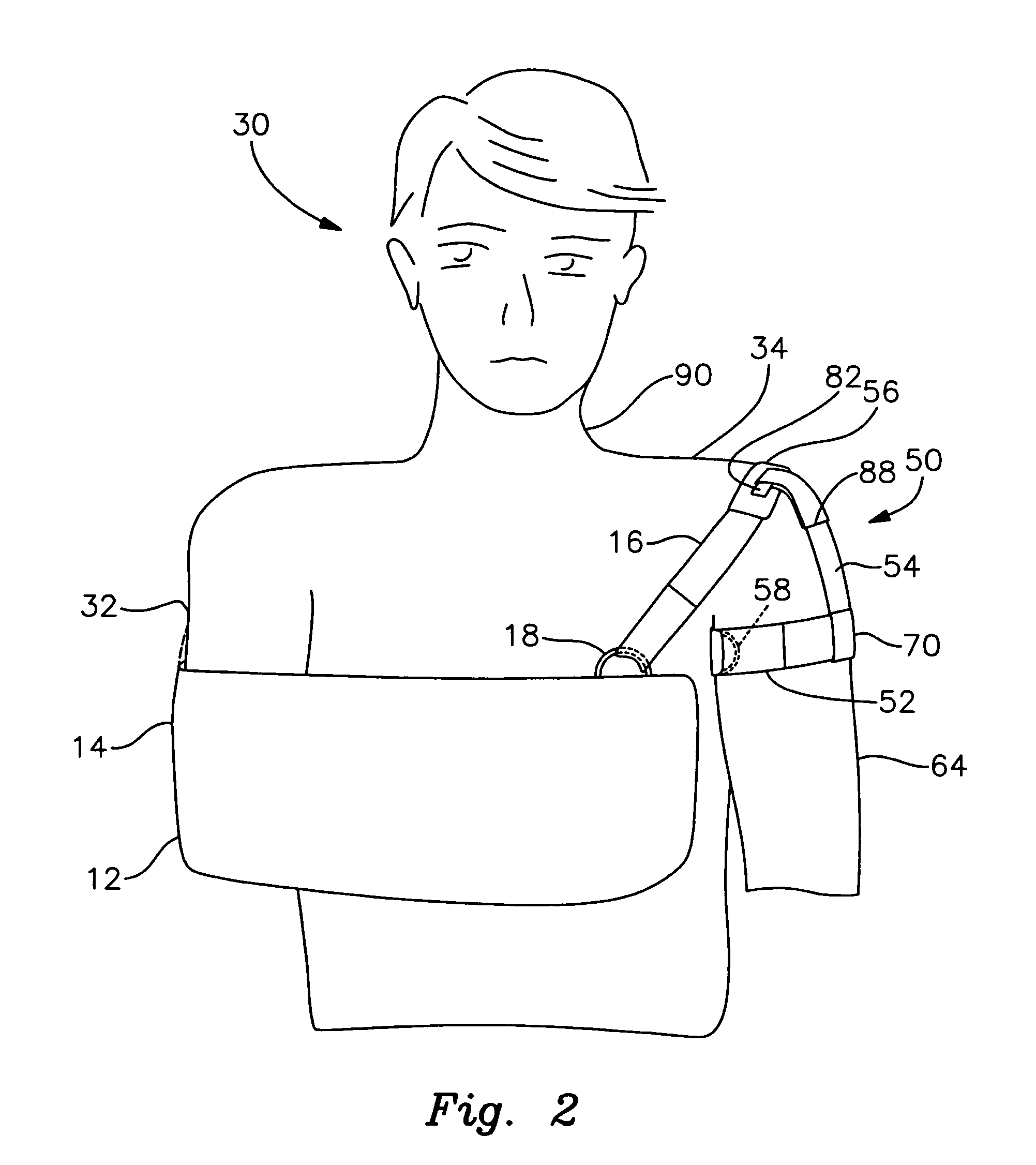
[0021]FIG. 2 is a front elevational view of a patient wearing an orthopedic sling in conjunction with one embodiment of the weight shifting constraint apparatus of this invention;

[0022]FIG. 3 is a top plan view of the armband;

[0023]FIG. 4 is a top plan view of the anchor strap;

[0024]FIG. 5 is a top plan view of the cushioning pad;

[0025]FIG. 6 is a perspective view of the apparatus with the components interengaged; the anchor strap and armband are not yet closed and are left open to more clearly illustrate the interengagement of those components with each other and with the cushioning pad;

[0026]FIG. 7 is a front elevational view of a patient wearing an orthopedic sling that is laterally adjusted by an alterna...


PUM


Abstract

An apparatus for laterally constraining the shoulder strap of an arm supporting orthopedic sling includes an armband for encircling and attaching to the well arm of the wearer and an anchor strap interconnected between the armband and the shoulder strap for pulling the shoulder strap laterally away from the wearer's neck and holding that strap such that the weight of the supported arm is borne at least primarily by the shoulder rather than the neck.

Description

RELATED APPLICATION[0001]This application claims the benefit of U.S. Provisional Patent Application Ser. No. 61 / 068,113 filed Mar. 4, 2008.FIELD OF THE INVENTION[0002]This invention relates to an apparatus for shifting or transferring the weight of an arm supported by an orthopedic sling so that such weight is borne largely by the shoulder rather than the neck of the wearer.BACKGROUND OF THE INVENTION[0003]Orthopedic slings have long been used to support a broken or otherwise injured arm. Such slings are also commonly utilized to support the arm in cases where the wearer has injured his or her shoulder, elbow, wrist or hand. Most orthopedic slings feature an elongate strap that is wrapped over the shoulder opposite the supported arm (i.e. the “well shoulder”). Unfortunately, this type of medical product exhibits a common and extremely annoying problem. The weight of the supported arm, which is often compounded by a cast, bandages, etc., typically causes the strap of the sling to exe...

Claims


Application Information

Patent Timeline
IPC IPC(8): A61F5/00
CPCA61F5/3738
Inventor WICKSTROM, CHRISTOPHER MICHAEL
Owner WICKSTROM CHRISTOPHER MICHAEL
Learn More