Direction controlling system and method of an electronic device
Active Publication Date: 2010-07-01
CHI MEI COMM SYST INC
14 Cites 76 Cited by
AI-Extracted Technical Summary
Problems solved by technology
However, the joystick may not be sensitive enough after the joystick is long ti...
Abstract
A direction controlling system and method of an electronic device provides a fingerprint identification device for a user to touch. The electronic device captures a fingerprint template image of a finger. When the finger moves on the fingerprint identification device, the electronic device captures a sequence of fingerprint images of the finger. Furthermore, the electronic device detects a directional movement of the fingerprint according to the sequence of fingerprint images and the fingerprint template image. A scroll bar of the electronic device is controlled to move according to the movement direction and a movement distance calculated by the electronic device.
Application Domain
Character and pattern recognitionCathode-ray tube indicators +1
Technology Topic
Control electronicsFingerprint +6
Image
Examples
- Experimental program(1)
Example
[0012]All of the processes described below may be embodied in, and fully automated via, functional modules executed by one or more general purpose processors. The functional modules may be stored in any type of computer-readable medium or other computer storage device. Some or all of the methods may alternatively be embodied in specialized computer hardware or communication apparatus.
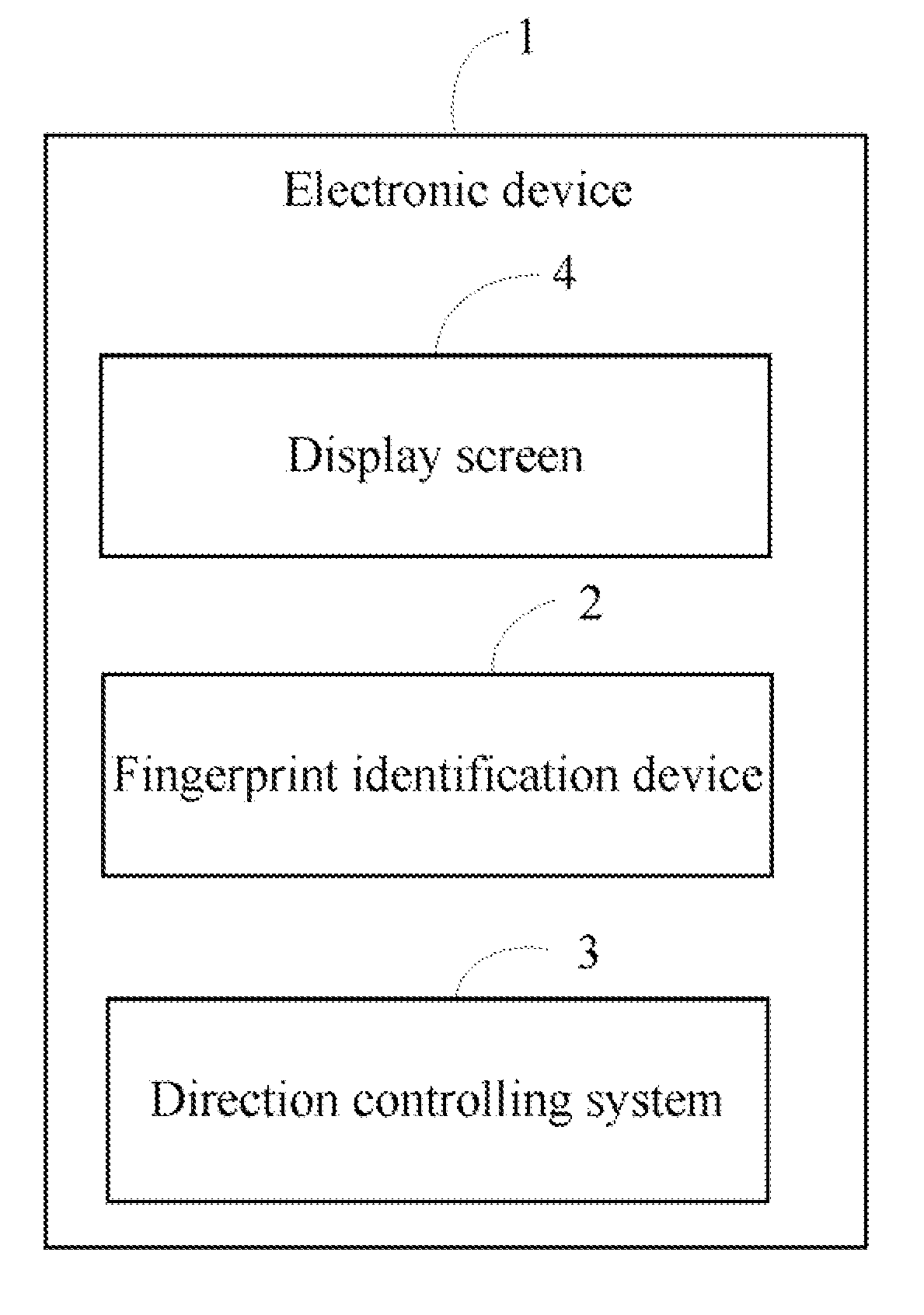
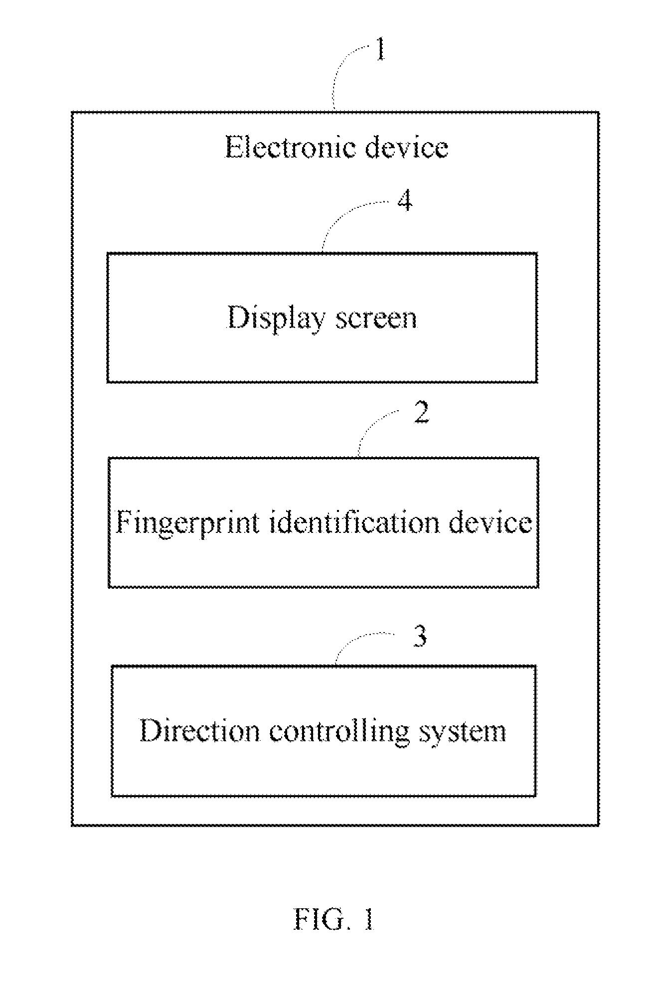
[0013]FIG. 1 is a block diagram of one embodiment of a direction controlling system 3 of an electronic device 1. The direction controlling system 3 is for controlling operation of the electronic device 1. In one embodiment, the electronic device 1 may be a mobile phone, or a notebook. The electronic device 1 includes a fingerprint identification device 2, and a display screen 4. In one embodiment, the identification device 2 may be a touch screen, so a finger should move on the identification device 2.
[0014]In one example, the current icon displayed on the display screen 4 is “phone book”. If a user wants to browser a next icon “short message”, the user must move the finger on fingerprint identification device 2 in a downward direction. The direction controlling system 3 obtains fingerprints of the finger, and detects the direction of the finger has moved. The direction controlling system 3 controls the “short message” icon displayed on the display screen 4. When a finger moves on the fingerprint identification device 2, the direction controlling system 3 captures a sequence of fingerprint images of the finger. Then the direction controlling system 3 determines a directional movement of the fingerprints according to the sequence of fingerprint images.
[0015]Furthermore, the direction controlling system 3 transforms the fingerprint images to fingerprint binary images. In one embodiment, the binary images may be monochrome images. The direction controlling system 3 reduces luminance of the binary images to contrast a fingerprint pattern and a background color in the fingerprint images. In one embodiment, the captured images may include three types: blank images, partially fingerprinted images, and fully fingerprinted images. A blank image does not include a fingerprint. A partially fingerprinted image is an image with a partial fingerprint pattern and blank areas. A full fingerprint image is an image fully encapsulating a fingerprint pattern. The partially fingerprinted image may be, but not limited to, a left fingerprinted image or a right fingerprinted image. A left fingerprinted image includes blank areas in a left side of the fingerprint image. A right fingerprinted image includes blank areas in a right side of the fingerprint image. As shown in FIG. 4, the fingerprint image 41 is a blank image, the fingerprint image 42 is a left fingerprinted image, the fingerprint image 43 is a right fingerprinted image, and the fingerprint image 44 is a fully fingerprinted image. In one embodiment, a size of the fingerprint identification device 2 is about 1*1 centimeter̂2 (cm̂2), which is smaller than a fingertip, thus it should be understood that there are blank areas in both in a left side and a right side in one fingerprint image.
[0016]FIG. 2 is a block diagram of one embodiment of function modules of the direction controlling system 3 in FIG. 1. In one embodiment, the direction controlling system 3 may include a scanning module 30, a detecting module 32, a calculating module 34, and a controlling module 36. It may be understood that one or more specialized or general purpose processors, such as a processor 38, may be used to execute one or more computerized codes of the function modules 30-36. The one or more computerized codes of the functional modules 30-36 may be stored in a storage system 40.
[0017]The scanning module 30 captures the sequence of fingerprint images when a finger moves on the fingerprint identification device 2. In one embodiment, the scanning module 30 captures four consecutive images. As shown in FIG. 5, the image 51, image 52, image 53, and image 54 are captured sequentially in a timely manner. The scanning module 30 also captures a fingerprint template image of the finger and stores the fingerprint template image in the storage system 40.
[0018]The detecting module 32 determines a directional movement of the fingerprints on the fingerprint identification device 2 according to the consecutive images and the fingerprint template image.
[0019]In one embodiment, the detecting module 32 detects if at least two consecutive images in the sequence of fingerprint images have blank areas. If at least two consecutive images have blank areas, the detecting module 32 computes if the finger moved in a leftward direction or in a rightward direction on the fingerprint identification device 2. If there are blank areas in a left side in each of the at least two consecutive images, the detecting module 32 determines that the finger has moved in a leftward direction on the fingerprint identification device 2. If there are blank areas in a right side in each of the at least two consecutive images, the detecting module 32 determines that the finger has moved in a rightward direction on the fingerprint identification device 2.
[0020]If no two consecutive images have blank areas, the detecting module 32 detects if there are any blank images in the fingerprint images. If there are no blank images in the fingerprint images, the detecting module 32 determines that the finger has moved in an upward direction or in a downward direction on the fingerprint identification device 2. If the fingerprint pattern in the first of the two consecutive images in the sequence of fingerprint images is at a higher position relative the fingerprint pattern in the following image in the consecutive images, the detecting module 32 determines that the finger has moved in the downward direction. If the fingerprint pattern in the first of the two consecutive images in the sequence of fingerprint images is at a lower position relative the fingerprint pattern in the following image in the consecutive images, the detecting module 32 determines that the finger has moved in the upward direction. For example, as shown in FIG. 6, the detecting module 32 records a fingerprint position L1 in the fingerprint template image corresponding to the fingerprint pattern in a fingerprint image which is captured first. Furthermore, the detecting module 32 records a fingerprint position L2 in the fingerprint template image corresponding to the fingerprint pattern in a fingerprint image which is captured last. If the fingerprint position L1 is higher than the fingerprint position L2, the detecting module 32 determines that the finger has moved in the downward direction on the fingerprint identification device 2. If the fingerprint position L1 is lower than the fingerprint position L2, the detecting module 32 determines that the finger has moved in the upward direction on the fingerprint identification device 2.
[0021]If there is at least one blank image in the fingerprint images, the detecting module 32 detects if there is only one full fingerprint image. If there is only one full fingerprint image, the detecting module 32 determines the fingerprint identification device 2 has been tapped. In one embodiment, that the fingerprint identification device 2 is tapped may be understood that the fingerprint identification device 2 is clicked by the finger. If there are at least two full fingerprint images, the detecting module 32 determines that the fingerprint identification device 2 has been double tapped.
[0022]The calculating module 34 calculates a movement distance “x” of the fingerprint, and calculates a displacement speed “v” of the fingerprint according to the movement distance “x”. A formula of calculating the displacement speed is as follows: v=x/t. The “t” denotes a time interval between two consecutive fingerprint images.
[0023]The calculating module 34 calculates a movement distance of a scroll bar on the display screen 4 of the electronic device 1 according to the displacement speed. In one embodiment, the scroll bar may be a vertical scroll bar and a horizontal scroll bar. If 0 <15 m/s and the finger moved in a leftward direction or a rightward direction, the scroll bar may move a distance of half of a width of the display screen 4. If 4 cm/s≦v≦15 m/s and the finger moved in an upward direction or a downward direction, the scroll bar may move a distance of half of a length of the display screen 4. If v 15 cm/s, the scroll bar may move a distance of the width or the length of the display screen 4, namely the display screen 4 may display a next page.
[0024]The controlling module 36 controls movement of the scroll bar according to the calculated movement distance.
[0025]FIG. 3 is a flowchart of one embodiment of a direction controlling method of an electronic device. Depending on the embodiment, additional blocks may be added, others removed, and the ordering of the blocks may be changed.
[0026]In block S30, the scanning module 30 captures a sequence of fingerprint images of when a finger moves on the fingerprint identification device 2.
[0027]In block S32, the detecting module 32 detects if at least two consecutive images in the sequence of fingerprint images have blank areas. If at least two consecutive images have blank areas, the procedure goes to S34.
[0028]In block S34, the detecting module 32 determines that the finger moved in a leftward direction or in a rightward direction on the fingerprint identification device 2. If there are blank areas in a left side in each of the at least two consecutive images, the detecting module 32 determines that the user finger has moved in a leftward direction on the fingerprint identification device 2. If there are blank areas in a right side in each of the at least two consecutive images, the detecting module 32 determines that the finger has moved in a rightward direction on the fingerprint identification device 2.f
[0029]In block S36, the calculating module 34 calculates a displacement speed “v” of the fingerprint. In one embodiment, the calculating module 34 calculates a movement distance “x” of the fingerprint. Then the calculating module 34 calculates the displacement speed “v” according to the movement distance “x”.
[0030]In block S38, the calculating module 34 calculates a movement distance of a scroll bar on the display screen 4.
[0031]In block S40, the controlling module 36 controls the scroll bar to move according to the calculated movement distance of the scroll bar.
[0032]In block S32, if no two consecutive images have blank areas, in block S42, the detecting module 34 detects if there are any blank images in the fingerprint images. If there are no blank images in the fingerprint images, the procedure goes to block S44. If there is at least one blank image in the captured image, the procedure goes to S46.
[0033]In block S44, the detecting module 32 determines that the finger has moved in an upward direction or in a downward direction, and the procedure returns to block S36. In one embodiment, as shown in FIG. 6, the detecting module 32 records a fingerprint position L1 in the fingerprint template image corresponding to the fingerprint pattern in a fingerprint image which is captured at first. Furthermore, the detecting module 32 records a fingerprint position L2 in the fingerprint template image corresponding to the fingerprint pattern in a fingerprint image which is captured at last. If the fingerprint pattern in the first of the two consecutive images in the sequence of fingerprint images is at a higher position relative the fingerprint pattern in the following image in the consecutive images, the detecting module 32 determines that the finger has moved in the downward direction. If the fingerprint pattern in the first of the two consecutive images in the sequence of fingerprint images is at a lower position relative the fingerprint pattern in the following image in the consecutive images, the detecting module 32 determines that the finger has moved in the upward direction.
[0034]In block S46, the detecting module 32 detects if there is only one full fingerprint image. If there is only one full fingerprint image, in block S48, the detecting module 32 determines that the fingerprint identification device 2 has been tapped. If there are at least two full fingerprint images, in block S50, the detecting module 32 determines that the fingerprint identification device 2 has been double tapped.
[0035]Although certain inventive embodiments of the present disclosure have been specifically described, the present disclosure is not to be construed as being limited thereto. Various changes or modifications may be made to the present disclosure without departing from the scope and spirit of the present disclosure.
PUM


Description & Claims & Application Information
We can also present the details of the Description, Claims and Application information to help users get a comprehensive understanding of the technical details of the patent, such as background art, summary of invention, brief description of drawings, description of embodiments, and other original content. On the other hand, users can also determine the specific scope of protection of the technology through the list of claims; as well as understand the changes in the life cycle of the technology with the presentation of the patent timeline. Login to view more.