Safety release for direct drive of rotary knife

a safety release and rotary knife technology, applied in the direction of couplings, manufacturing tools, tableware, etc., can solve the problems of limiting the rotation of the annular blade within the knife housing, and affecting the safety of rotary knives

Active Publication Date: 2010-07-08
HANTOVER
View PDF12 Cites 47 Cited by
  • Summary
  • Abstract
  • Description
  • Claims
  • Application Information

AI Technical Summary

Benefits of technology

[0006]Embodiments of the present invention provide a safety release for a shaft drive that does not suffer from the problems and limitations of the prior art shaft drives set forth above.

Problems solved by technology

Conventional rotary knives are problematic and suffer from certain limitations.
One problem encountered by prior art knives is that the annular blade within the knife housing can be restricted from rotating during operation.
For instance, a bone or other obstruction encountered while dressing a carcass can become lodged between the blade and housing and either slow blade rotation or entirely stop the blade.
Also, the annular blade and other components of the rotary knife can become worn from extensive use and cause the blade to bind within the housing.
During installation, the annular blade can become misaligned within the housing and blade misalignment can also cause excessive wear of knife components and binding of the blade.
For shaft-driven rotary knives, binding of the blade or shaft is known to expose the elongated flexible shaft to a significant amount of torque and cause the flexible shaft to twist or move unexpectedly.
However, these conventional rotary knives are not ergonomically designed and are known to cause the operator to experience fatigue in the hand and arm from holding the knife and depressing the lever over a long period of time (e.g., a user will operate the same knife for an eight hour work day, five days per week).

Method used


Image

  • Safety release for direct drive of rotary knife
  • Safety release for direct drive of rotary knife
  • Safety release for direct drive of rotary knife

Examples


Embodiment Construction

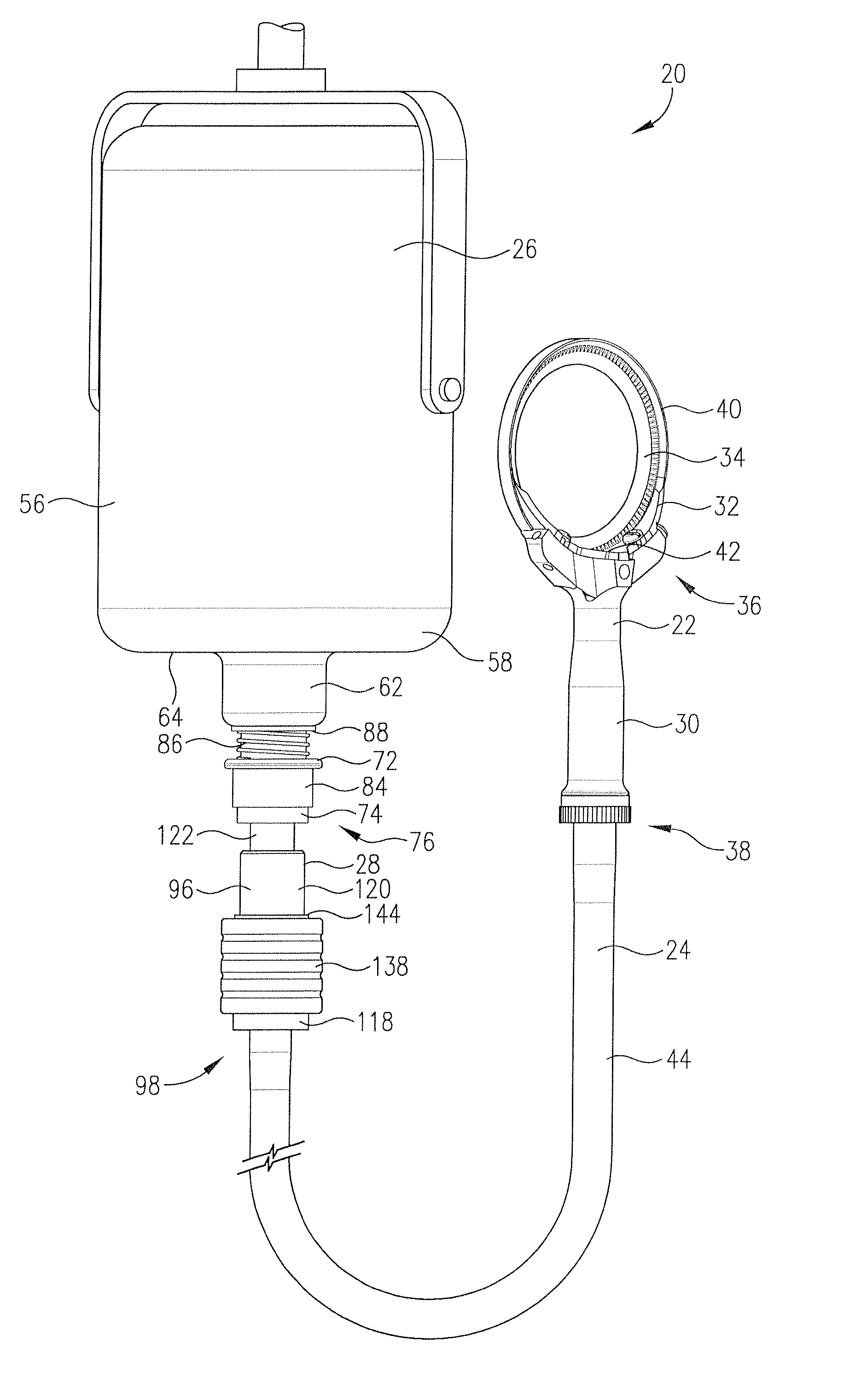
[0020]Turning initially to FIG. 3, a powered rotary knife assembly 20 is configured to be used in an animal slaughterhouse for dressing an animal carcass, although other knife applications are entirely within the ambit of the present invention. The rotary knife assembly 20 broadly includes a rotary knife 22, a flexible drive cable 24, a motor 26, and a safety coupling 28 that are drivingly connected to one another, with power being transmitted from the motor 26 to the rotary knife 22 by the drive cable 24 and safety coupling 28.

[0021]The rotary knife 22, depicted in FIG. 3, is a conventional rotary knife operable for trimming, boning, and cutting the animal carcass. The rotary knife 22 includes a handle 30, a blade housing 32, and a rotating annular blade 34. The handle 30 presents a front blade support end 36 and a rear connector end 38 that connects to the drive cable 24. The handle 30 further includes a transmission (not shown) with a transmission input end positioned adjacent th...


PUM


Abstract

A rotary knife assembly includes a rotary knife with a spinning blade, a motor operable to power the rotary knife, a flexible drive cable with a proximal end drivingly connected to the knife to transmit rotational power to the blade while being flexed along the length of the cable, and a safety release drivingly connected to a distal end of the cable. The safety release is drivingly coupled to the motor and is operable to transmit rotational power from the motor to the drive cable and thereby the rotary knife. The safety release includes input and output members releasably drivingly engaged with one another. The safety release is operable to drivingly disengage the members.

Description

BACKGROUND[0001]1. Field[0002]The present invention relates generally to a safety release for a shaft drive. More specifically, embodiments of the present invention concern a safety release for use with a powered rotary knife.[0003]2. Discussion of Prior Art[0004]Powered knifes have long been used in the meat processing industry for dressing an animal carcass. The process of dressing the carcass normally involves removing meat and fat from various bones (i.e., boning), cutting various bones, and trimming the meat. Powered rotary knives enable workers to perform this process with much greater efficiency than traditional, unpowered knives. Among these prior art powered knives are rotary knives that include a rotating annular blade rotatably driven within a knife housing. Rotary knives can be either electrically or pneumatically powered and are able to spin the annular blade at very high rotational speeds. Electrically powered rotary knives include an electric motor and a flexible driv...

Claims


Application Information

Patent Timeline
Patent Type & Authority Applications(United States)
IPC IPC(8): A22C17/00B26B25/00
CPCA22B5/165B26B25/002Y10T403/591Y10T403/18
Inventor LEVSEN, CLARK A.
Owner HANTOVER
Why Eureka
Try Eureka