
Method and Machine for Cutting Blinds

Active Publication Date: 2010-07-08
LUMINO
View PDF24 Cites 3 Cited by
  • Summary
  • Abstract
  • Description
  • Claims
  • Application Information

AI Technical Summary

Benefits of technology

[0009]We provide a window covering cutting machine comprising a cutting mechanism that has a housing with at least one opening sized to receive at least a portion of a window covering, a window covering support surface adjacent the one or more openings, a clamp support positioned adjacent that one or more openings, a hand screw that has a threaded shaft that passes through a threaded opening in the clamp support, a clamp block positioned adjacent the threaded shaft and a spring betwe

Problems solved by technology

Such custom sized blinds are often expensive.
The machines that have been used to cut down Venetian blinds, vertical blinds, pleated shades and cellular shades are difficult or impossible to use for cutting down woven wood blinds.
These blinds cannot be cut with cutting dies.
Straight blades or circular blades may not make even cuts or may crack or splinter the blind if the woven wood blind is not securely held.
Although clamps have been used to secure other types of blinds in a cut-down machine, clamps are difficult to use on woven wood shades.
For these reasons, woven wood shades are difficult to clamp securely and can be easily damaged when clamped.
If the middle of a woven wood blind is clamped, the ends of the blind may bulge out.
If too much pressure is exerted the wood strips, wood sticks or lengths of glass may split or splinter.
However, this method of cutting woven wood blinds has generally not been adopted by retailers or fabricators of woven wood or woven grass blinds.
One problem with wrapped blinds is that they can still flex or change shape during the cutting process which results in an uneven cut.
But the use of spacer material has not solved the problem.
Cut edges may be rough or uneven.

Method used


Image

  • Method and Machine for Cutting Blinds
  • Method and Machine for Cutting Blinds
  • Method and Machine for Cutting Blinds

Examples


Embodiment Construction

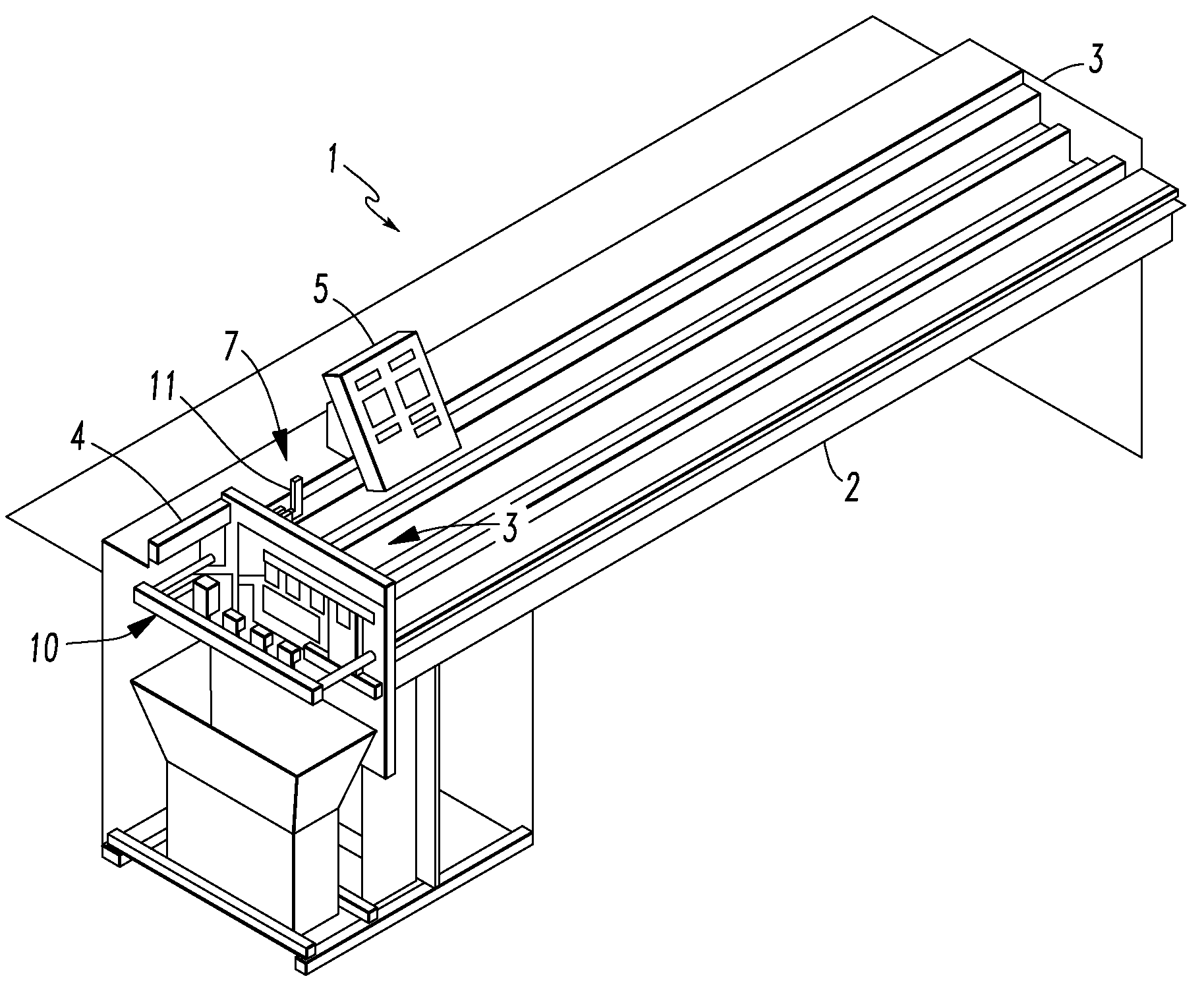
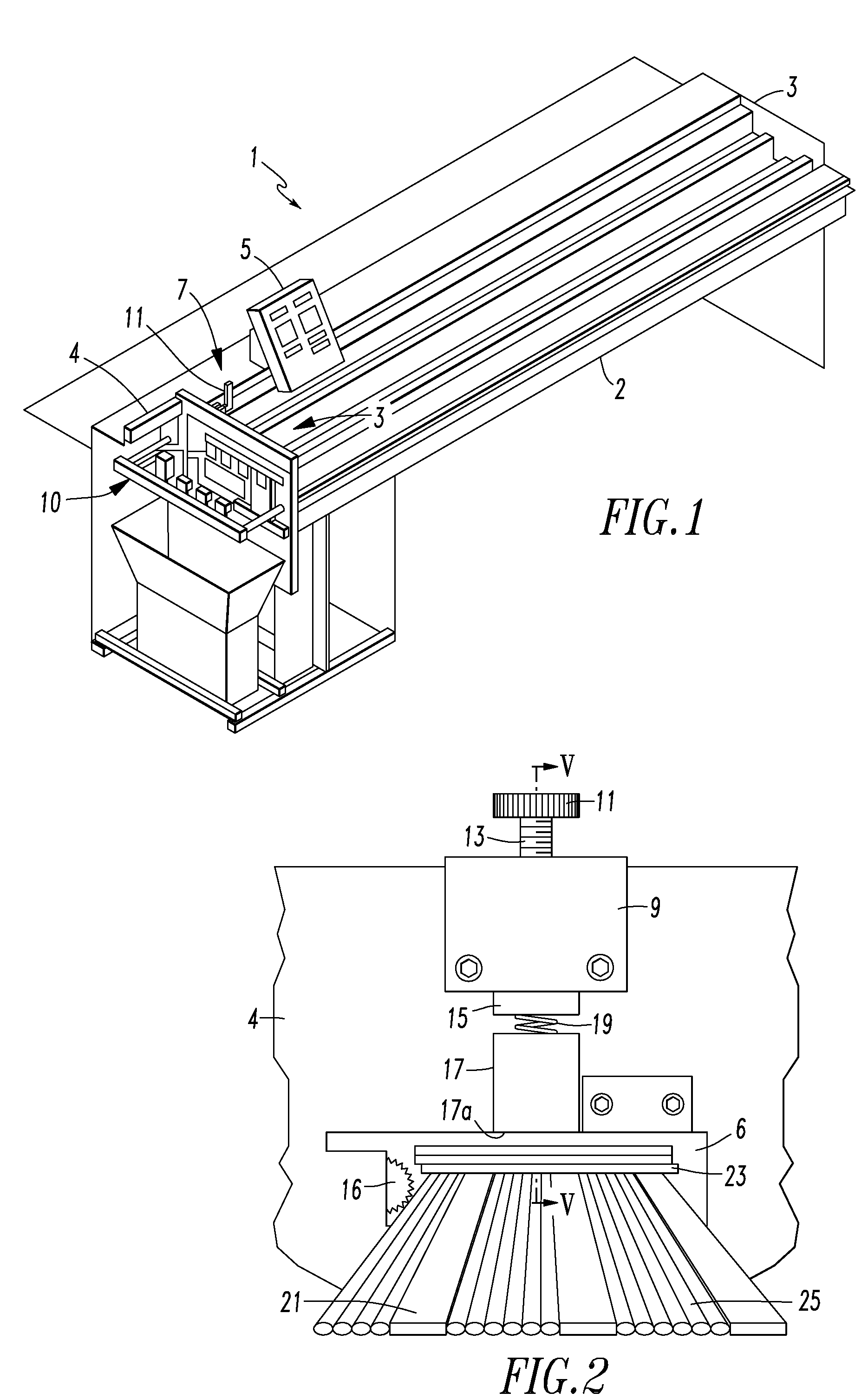
[0028]Referring to FIG. 1, a first present preferred embodiment of my blind cutting machine 1 includes a support surface 2 that is sized to support a window covering to be cut down by the machine 1. The machine 1 also includes a cutting mechanism 3 connected to the support surface 2. The cutting mechanism 3 includes a housing 4 that has at least one opening 6, a cutting device 16 and a clamping device 7. The cutting device 16 may be a straight blade or a circular saw blade suitable for trimming a woven wood blind. An end stop 10 is connected to the cutting mechanism 3 and is configured to move to abut an end of a work piece extending through an opening 6 in the cutting mechanism 3. The end stop 10 may be dynamically braked to stop the movement of the end stop 10 when it is positioned to engage a work piece. Preferably, the end stop 10 is actuated by one rod or piston to better facilitate dynamic braking of the end stop 10. A carrier 8 (shown in dotted line in FIG. 1) may be provided...


PUM

PropertyMeasurementUnit
Pressureaaaaaaaaaa

Abstract

A method and machine for cutting woven wood blinds is disclosed. The disclosed machine can include a cutting mechanism, a support surface adjacent at least one opening in the cutting mechanism housing, a spring loaded clamp which engages the woven wood blind to hold the blind securely for cutting without damaging the blind. The clamp is preferably operated by a hand screw. An indicator such as a collar attached to the hand screw is provided to tell the user when the clamp is positioned to provide the desired pressure. The disclosed method can include positioning a window covering into a cutting machine, positioning a first cutting support member on the window covering, moving a clamp to engage the first cutting support member and cutting the window covering.

Description

FIELD OF INVENTION[0001]The present invention relates to blind cutting machines and methods of cutting or trimming blinds, particularly woven wood and woven grass blinds.BACKGROUND OF INVENTION[0002]Woven wood blinds have recently grown in popularity. Such blinds contain strips or sticks of wood or faux wood or lengths of grass or grasses laid side by side and woven together to form a panel. The panel of woven wood or grass extends from a board or headrail and may be raised or lowered by a lift mechanism. Typically the lift mechanism is comprised of a set of cords that pass through a cord lock. In a roll-up shade, each cord runs from the headrail down the one side of the panel and up the other side. In a roman shade, the lift cords run behind the panel from a point near the bottom of the shade to and through the cord lock. Examples of such blinds are disclosed in U.S. Pat. Nos. 7,353,856, 6,860,312 and U.S. Patent Application Publication Nos. 2007 / 0175783 and 2007 / 0175782. The phras...

Claims


Application Information

Patent Timeline
IPC IPC(8): B26D7/02B26D7/27B26D7/01B26D1/00
CPCB26D7/04E06B9/266Y10T83/7487Y10T29/39Y10T83/7647Y10T83/04Y10T83/849
Inventor KOLLMAN, MICHAEL
Owner LUMINO
Features
  • Generate Ideas
  • Intellectual Property
  • Life Sciences
  • Materials
  • Tech Scout
  • Unparalleled Data Quality
  • Higher Quality Content
  • 60% Fewer Hallucinations
Learn More