Active tension device for a window covering

a technology of active tension and window covering, which is applied in the direction of curtain suspension devices, door/window protective devices, hoisting equipment, etc., can solve the problems of loss of the advantages of the tension device, the drawback of the nevins invention and other current tension devices, and the unsafeness of the closed end and open end control cords

Inactive Publication Date: 2011-04-26
ROLLERASE INC
View PDF15 Cites 57 Cited by
  • Summary
  • Abstract
  • Description
  • Claims
  • Application Information

AI Technical Summary

Benefits of technology

[0006]The present invention provides a window covering with a tensioning device arranged so that the window covering is inoperable unless the tensioning device is properly installed. The tensioning device includes a drive mechanism with two different sections. A first section that is non-keyed and a second section that is keyed. The non-keyed section has fingers which are used to engage the drive wheel and casing and prevent relative rotation between those two elements. The non-keyed section is provided to allow relative rotation between the element it is engaged with and the element the keyed section is engaged with. This way, relative rotation of the wheel and casing can be allowed or prevented based on the positioning of a drive stud.
[0008]When the tension device is installed, a force is applied to the drive stud compressing the spring. This pushes the drive stud deeper into the device and then through the anchoring arm. Ramped ridges at the end of the fingers allow the fingers to pass through the specially designed hole in the anchoring arm, but not to pass back in the opposite direction. The drive stud is now in a position such that the keyed section is engaged with the anchoring arm and the back side of the outer casing, but not the drive wheel. Therefore the drive wheel is free to rotate relative to the casing, allowing the window covering to operate properly.

Problems solved by technology

Both the closed end and open end control cords could be unsafe.
But there is a major drawback to the Nevins invention and other current tension devices.
When this happens, the advantages of the tension device are lost.

Method used


Image

  • Active tension device for a window covering
  • Active tension device for a window covering
  • Active tension device for a window covering

Examples


Embodiment Construction

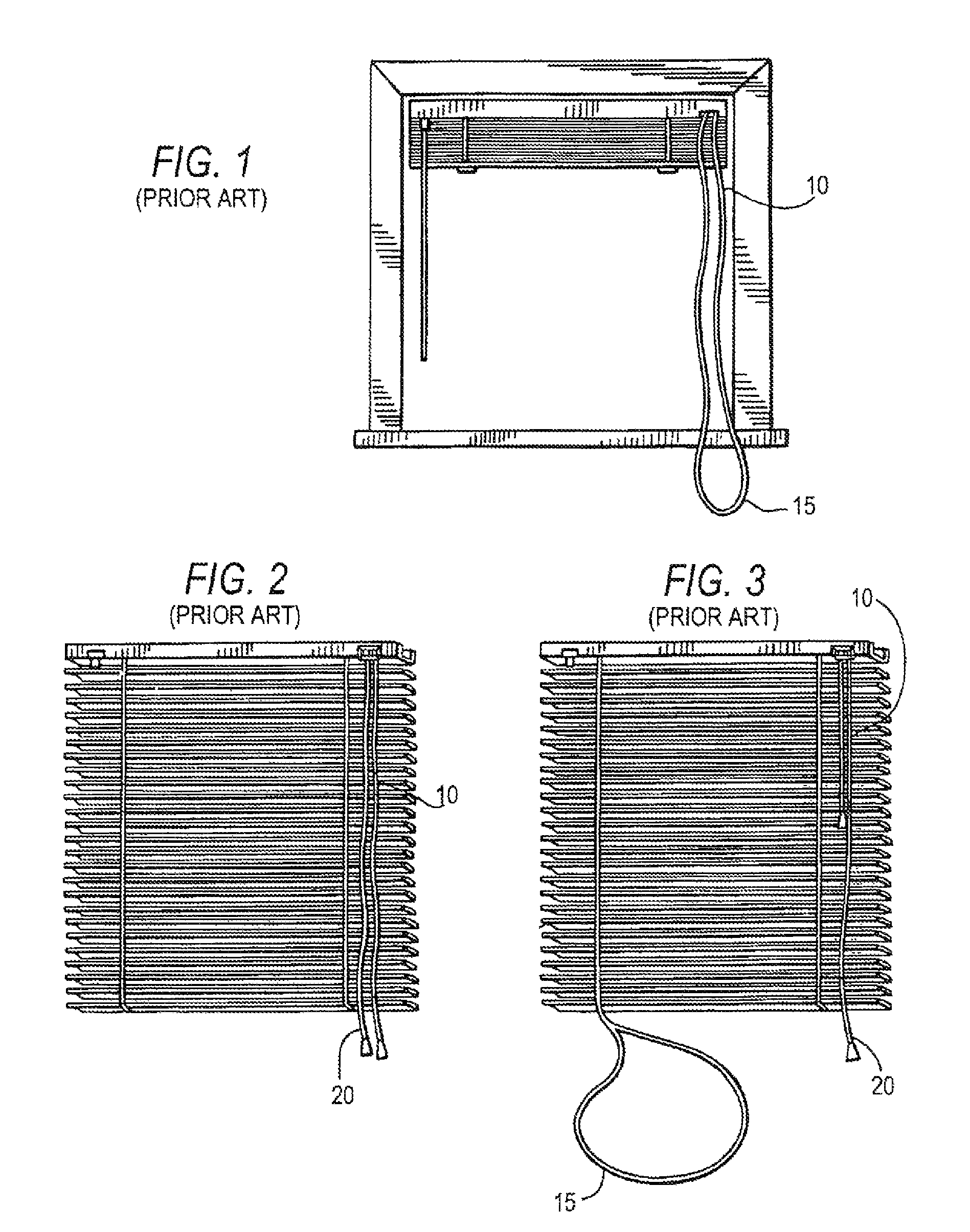
[0017]FIG. 1 shows a known window covering where the control cord 10 is not attached to a tension control device. Instead, the cord is loose and forms a loop 15 at its lower most section.

[0018]FIG. 2 shows a known window covering with control cords 10 having two open ends 20.

[0019]FIG. 3 shows another situation in which it is also possible for cords used to hold the window covering in place may become loose and form a loop 15.

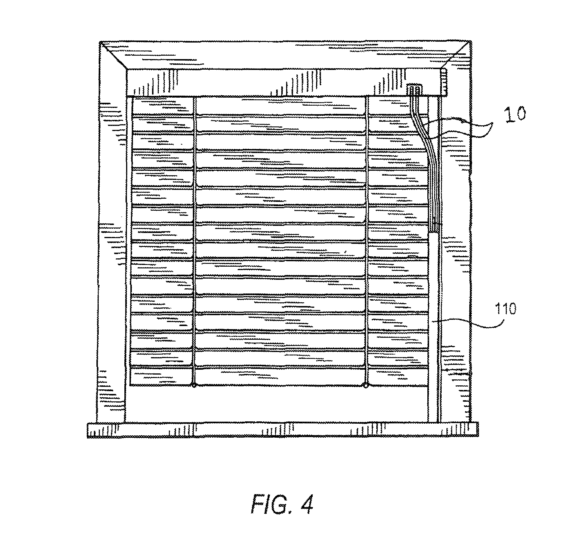
[0020]FIG. 4 shows a prior art tensioning device. This device incorporates a sleeve 110, in which the control cord 10 is encased. This system is effective at preventing a loop from forming in the control cords as seen in FIGS. 1-3. But this system requires significant labor to be installed. The sleeve must be installed separately from the window covering and the window covering could be installed without the sleeve and still operate properly.

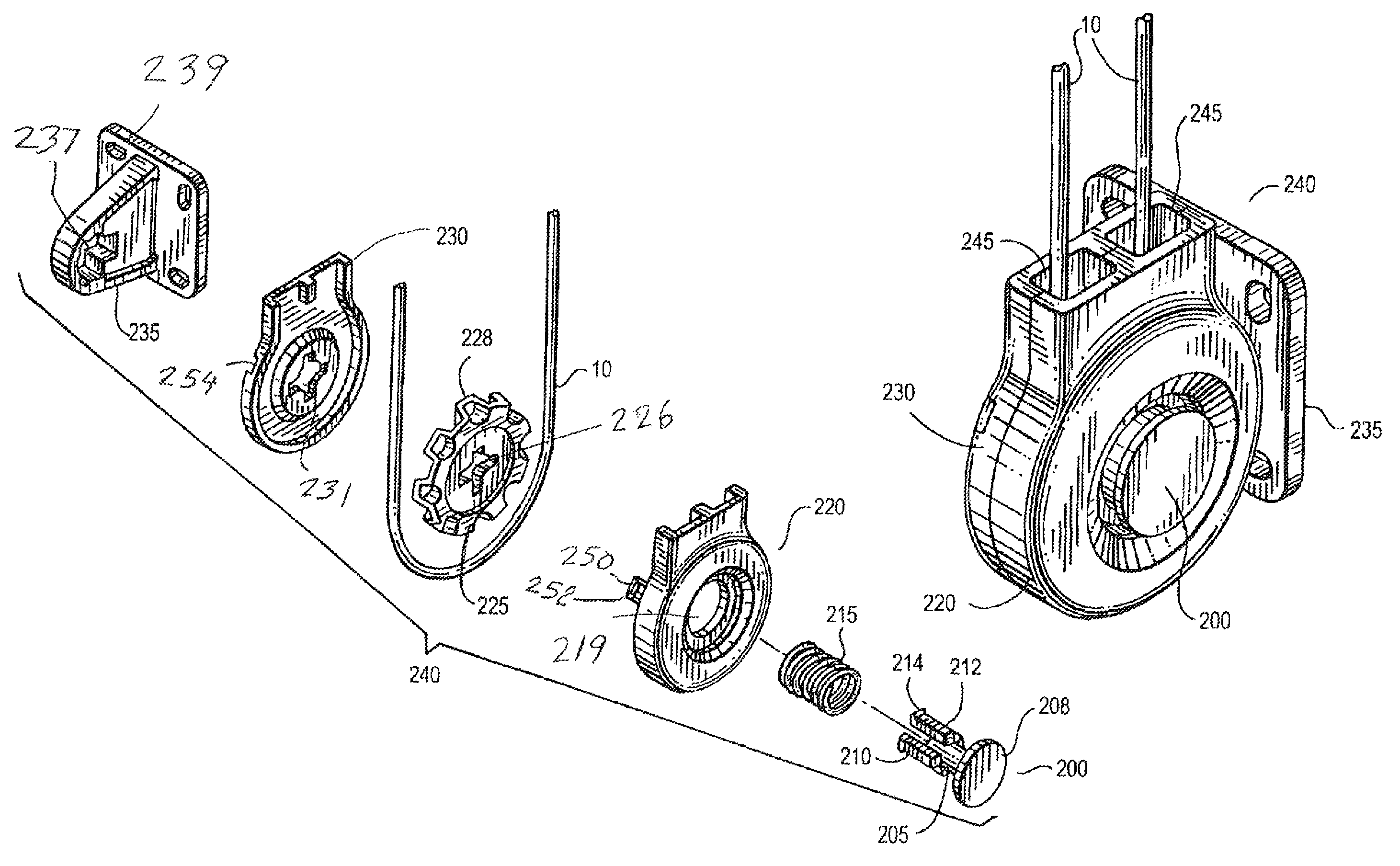
[0021]FIGS. 5-7 describe the preferred embodiment of the present invention. The tension device 240 includes a drive stud ...


PUM


Abstract

A tension device that prevents a window covering from operating properly until the tension device is installed. The tension device incorporates a drive wheel, casing, anchoring arm and drive stud. The drive stud has two sections, one keyed and one cylindrical. Before the tension device is installed, the keyed section of the drive stud engages the drive wheel and the casing, thereby preventing them from rotating relative to each other. When the tension device is installed, the drive stud must be inserted into the anchoring arm causing the keyed section of the drive stud to disengage the drive wheel and thereby allow the drive wheel to rotate relative to the casing.

Description

FIELD OF THE INVENTION[0001]This application relates generally to a tension device for tensioning the cord used to operate a window covering, and more particularly to a tension device that is adapted to prevent the window covering from operating properly prior to installation of the tension device.BACKGROUND OF THE INVENTION[0002]Modern window coverings can be raised and lowered for selectively blocking or filtering light in a room. A common method of achieving this result is through the use of one or more control cords. Some control cords have open ends, while others form a closed loop or end.[0003]Both the closed end and open end control cords could be unsafe.[0004]It is also possible for the cords on the opposite side of the control cord to become loose and create a loop large enough to fit the head of a child or pet as is shown in FIG. 3.[0005]One example of a prior art tension device is disclosed in U.S. Pat. No. 6,463,987 to Nevins. But there is a major drawback to the Nevins ...

Claims


Application Information

Patent Timeline
Patent Type & Authority Patents(United States)
IPC IPC(8): E06B9/305E06B9/30E06B9/00E06B9/388E06B9/386A47H1/00F16H55/36
CPCE06B9/38E06B9/322
Inventor CANNAVERDE, JOEREDIN, ROGER
Owner ROLLERASE INC
Why Eureka
Try Eureka