Automated lighting and building control system

a technology of automatic lighting and building control, applied in adaptive control, program control, instruments, etc., can solve the problems of inability to save money, inhibit the efficiency of the system, and the impracticality of using a portable light sensor

Inactive Publication Date: 2010-07-20
TLC INTEGRATION
View PDF10 Cites 58 Cited by
  • Summary
  • Abstract
  • Description
  • Claims
  • Application Information

AI Technical Summary

Benefits of technology

[0001]The present invention relates generally to automated lighting controllers and more particularly to an automated lighting and building control system that is operative to control a large number of lights and other control systems, such as security systems, powered window coverings, and HVAC systems, within a geographic area based on a large amount of input data, including day light conditions, occupancy data, security information, HVAC data, etc. The present invention also facilitates the remote control of the system over an Internet connection.

Problems solved by technology

Aside from the impracticality of relying on a portable light sensor to read daylight levels in the controlled space, the Paton system is also limited by the manner in which the controller communicates with the ballasts.
When a large number of ballasts are being controlled, the amount of data becomes enormous and overwhelms the controller, or at least significantly slows the operation of the system, thereby inhibiting the efficiency of the system and its ability to save money by controlling the amount of light being used at any given point in time.
As noted above, the use of a portable light sensor is impractical because light levels within a controlled space with windows or skylights change constantly as a day goes by and someone cannot be economically employed to walk around all day testing light levels.
Likewise, atmospheric conditions, such as clouds passing before the sun, can cause short to long-term changes in the amount of available daylight.
Moreover, it is not enough to just control the lights in a room, especially one with many windows or skylights, because sometimes too much daylight will be let in.
A primary disadvantage of such occupancy sensors is that they often incorrectly turn on the lighting system, referred to as a false on or nuisance on.
Unfortunately, the triple technology sensors available on the market are not easily adapted for use in lighting / building control systems.

Method used


Image

  • Automated lighting and building control system
  • Automated lighting and building control system
  • Automated lighting and building control system

Examples


Embodiment Construction

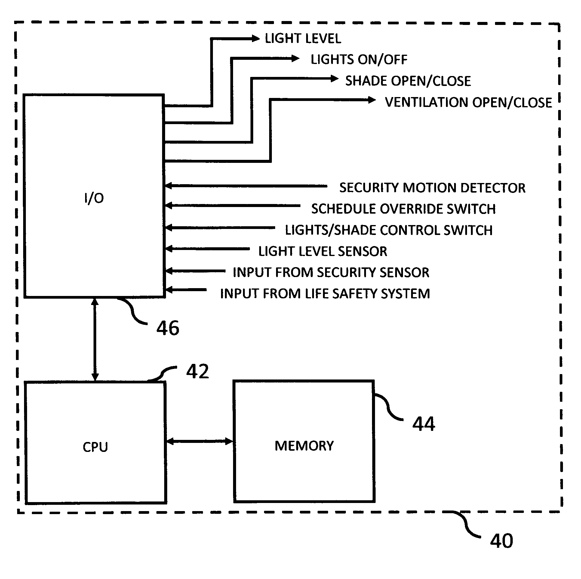
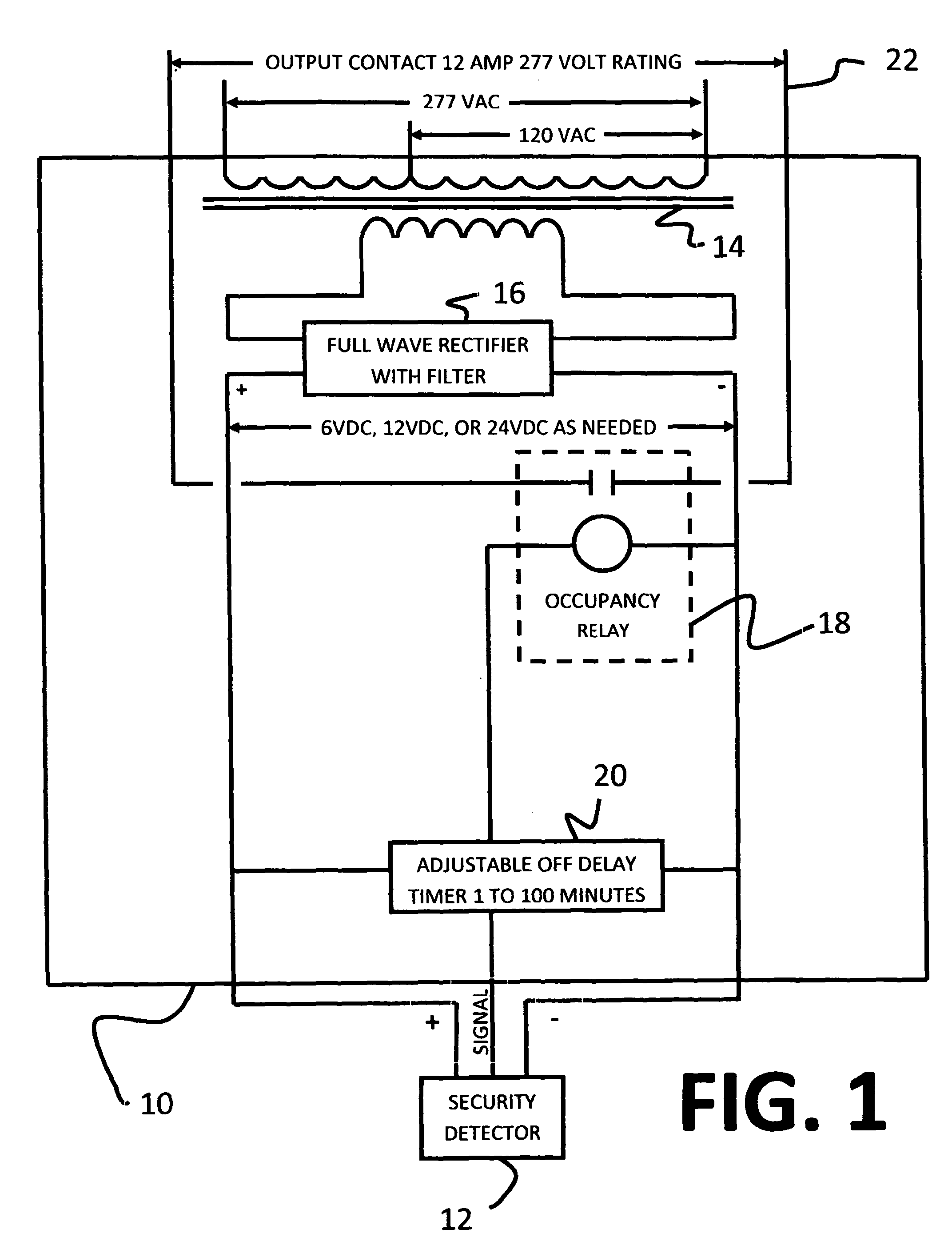
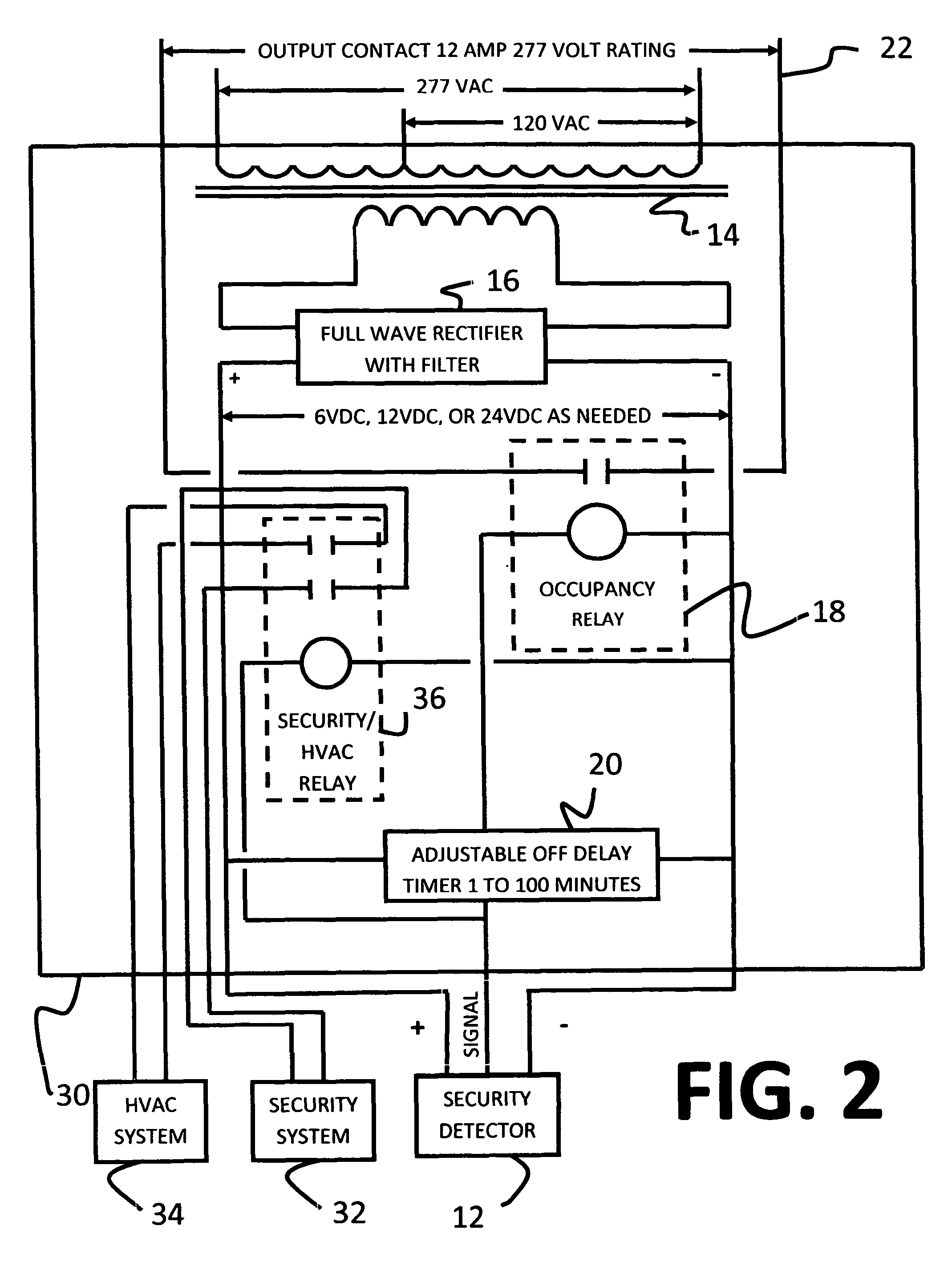
[0012]The present invention relates generally to automated lighting controllers and more particularly to an automated lighting and building control system that is operative to control a large number of lights and provide common control signals to other control systems, such as security systems, powered window coverings, and HVAC systems, within a geographic area based on a large amount of input data, including day light conditions, occupancy data, security information, HVAC data, etc. The savings generated by the control system are measurable and verifiable and enable the operator of the controlled space to analyze exactly how the controlled space is being utilized. To improve the quality of the overall control system, the present invention utilizes a universal occupancy adapter for converting any motion detector for a security system, into a component of the lighting / building controller. Further, the entire system can be controlled remotely over the Internet without the need for sp...


PUM


Abstract

An automated lighting and building control system that is operative to control a large number of lights and to provide control to other control systems, such as security systems, powered window coverings, and HVAC systems, within a geographic area based on a large amount of input data, including day light conditions, occupancy data, security information, HVAC data, etc. The savings generated by the control system are measurable and verifiable and enable the operator of the controlled space to analyze exactly how the controlled space is being utilized. To improve the quality of the overall control system, the present invention utilizes a universal occupancy adapter for converting any motion detector for a security system, into a component of the lighting / building controller. Further, the entire system can be controlled remotely over the Internet without the need for special software.

Description

BRIEF DESCRIPTION OF THE INVENTION[0001]The present invention relates generally to automated lighting controllers and more particularly to an automated lighting and building control system that is operative to control a large number of lights and other control systems, such as security systems, powered window coverings, and HVAC systems, within a geographic area based on a large amount of input data, including day light conditions, occupancy data, security information, HVAC data, etc. The present invention also facilitates the remote control of the system over an Internet connection.BACKGROUND OF THE INVENTION[0002]A number of lighting control systems have been developed that sense the amount of daylight in a room or building (a “controlled space”) and automatically adjust the lumen output of lights installed, typically fluorescent lights, in that controlled space to save money on energy expenses. U.S. Pat. No. 7,190,126 (“Paton”) provides an example of a daylight control system, wh...

Claims


Application Information

Patent Timeline
Patent Type & Authority Patents(United States)
IPC IPC(8): G05D23/00E05F15/20
CPCG05B15/02H05B37/0218H05B37/0227H05B37/0254H05B37/0281G05B2219/25168G05B2219/2642Y02B20/42Y02B20/44Y02B20/46H05B47/18H05B47/11H05B47/16Y02B20/40H05B47/115
Inventor KELLER, CARLFREEMAN, JR., JAMES MCLELLEN
Owner TLC INTEGRATION
Why Eureka
Try Eureka