Electromagnetic lock

Inactive Publication Date: 2010-07-08
GIANNI INDS
View PDF12 Cites 11 Cited by
  • Summary
  • Abstract
  • Description
  • Claims
  • Application Information

AI Technical Summary

Benefits of technology

[0012]The primary objective of the present invention is to provide an electromagnetic lock including a mounting structure for allowing the electromagnetic door lock device to be easily and quickly mounted or attached or secured to the supporting structures or walls or members or devices.
[0013]In accordance with one aspect of the invention, there is provided an electromagnetic door lock device comprising a mounting plate including at least one aperture formed therein for receiving a first fastener and for mounting the mounting plate to a supporting device, and the mounting plate including at least one protrusion extended therefrom and including a screw hole formed in the protrusion, a housing including at least one passage formed therein and aligned with the protrusion and the screw hole of the mounting plate for quickly anchoring and positioning the housing to the mounting plate, and a second fastener engaged through the passage of the housing and engaged with the screw hole of the mounting plate for easily securing the housing to the mounting plate.

Problems solved by technology

However, the electromagnet and the mounting brackets and the locking plates include a heavy weight that may not be easily held by the user while attaching or securing the electromagnet and the mounting brackets and the locking plates onto the supporting members, door panels, door frames, cabinets, walls or the like.
However, the electromagnet also includes a heavy weight that may not be easily held by the user while attaching or securing the electromagnet onto the supporting members, door panels, door frames, cabinets, walls or the like.

Method used


Image

  • Electromagnetic lock
  • Electromagnetic lock
  • Electromagnetic lock

Examples


Embodiment Construction

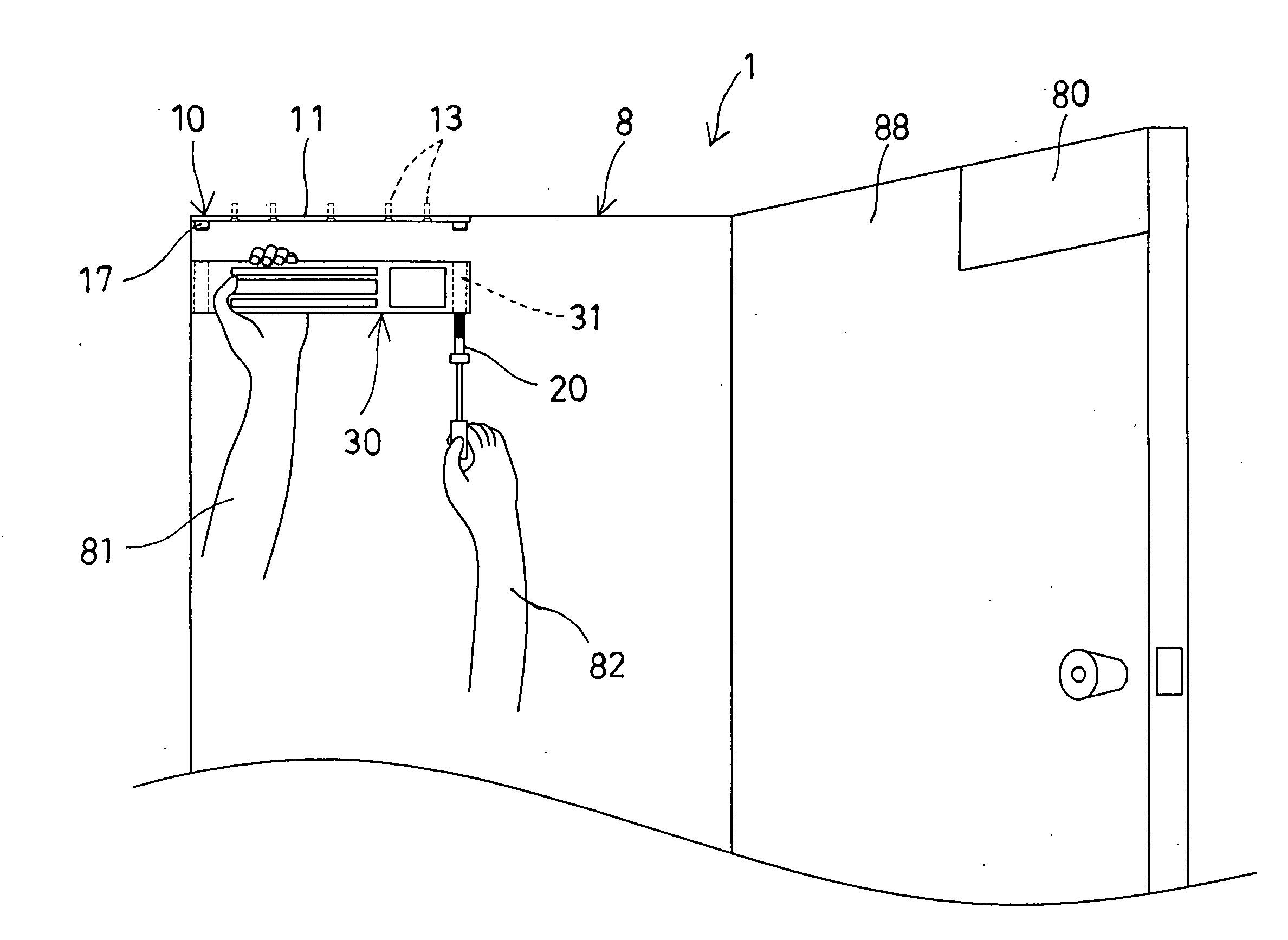
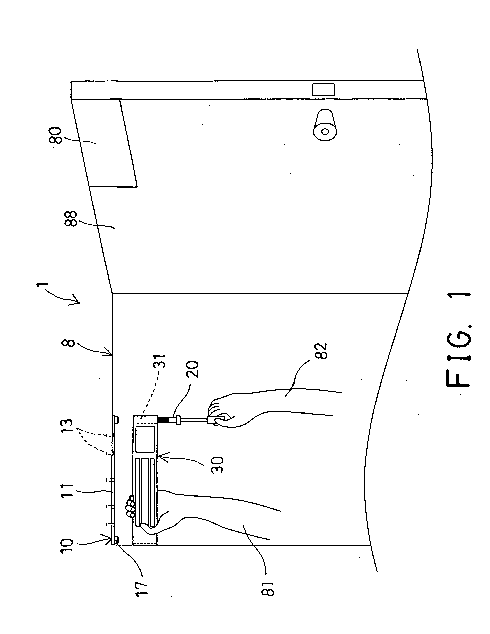
[0026]Referring to the drawings, and initially to FIGS. 1, 2 and 7, an electromagnetic lock 1 in accordance with the present invention comprises an electromagnetic device 10 provided for being mounted or attached or secured to a supporting structure or member or device 8, such as a door panel, a door frame 8, a cabinet, a wall member or the like, for acting or actuating or operating with an electromagnetic plate or armature plate 80 which is provided for being mounted or attached or secured to another supporting structure or member or device 88, such as a door frame, a cabinet, a wall member, a door panel 88, or the like, and arranged for allowing the electromagnetic device 10 and the armature plate 80 to be acted or actuated or operated with each other in order to selectively lock the door panel 88 to the door frame 8, or to selectively release the door panel 88 from the door frame 8.

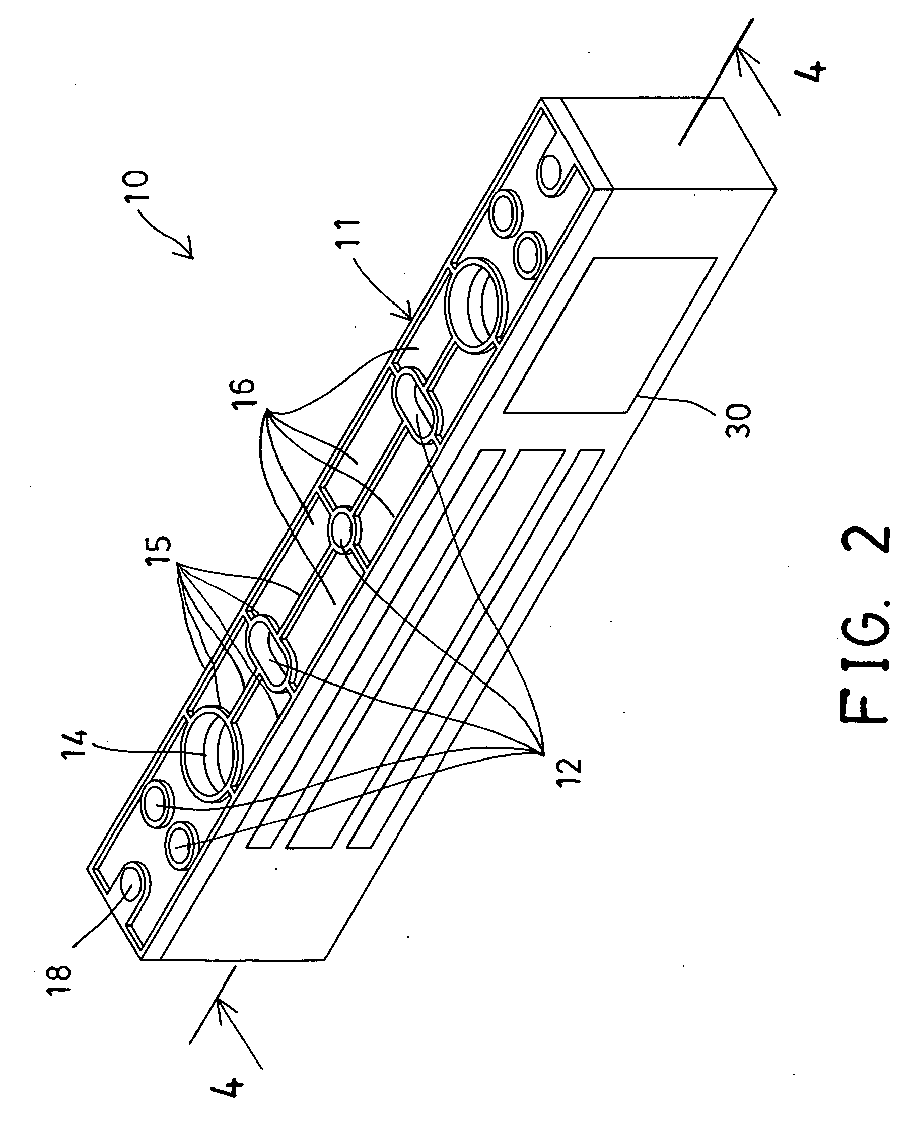
[0027]The electromagnetic device 10 includes a mounting plate 11 having one or more apertures 12 fo...


PUM


Abstract

An electromagnetic lock includes a mounting plate for attaching to a supporting device and the mounting plate includes one or more protrusions each having a screw hole, a housing includes one or more passages aligned with the protrusions and the screw holes of the mounting plate for quickly anchoring and positioning the housing to the mounting plate, and a fastener is engaged through each passage of the housing and engaged with the screw hole of the mounting plate for easily and quickly securing the housing to the mounting plate and for preventing the housing from being held by the user for a long time.

Description

BACKGROUND OF THE INVENTION[0001]1. Field of the Invention[0002]The present invention relates to an electromagnetic lock, and more particularly to an electromagnetic door lock device including a mounting structure for allowing the electromagnetic door lock device to be easily and quickly mounted or attached or secured to the supporting structures or walls or members or devices.[0003]2. Description of the Prior Art[0004]Typical electromagnetic door lock devices comprise an electromagnetic device and an armature plate or the like to be mounted or attached or secured to the supporting structures or members or devices, such as the door panels, the door frames, the cabinets, the walls or the like, and arranged for allowing the electromagnetic device and the armature plate to be acted or actuated or operated with each other in order to selectively lock the door panels to the door frames, or to selectively release the door panels from the door frames.[0005]For example, U.S. Pat. No. 4,826,...

Claims


Application Information

Patent Timeline
IPC IPC(8): E05C19/16
CPCE05B9/08E05C19/166Y10T292/11
Inventor CHANG, CHIH CHUNG
Owner GIANNI INDS
Why Eureka
Try Eureka