Helmet

Active Publication Date: 2018-12-20
CHEN TZU CHIANG
View PDF0 Cites 2 Cited by
  • Summary
  • Abstract
  • Description
  • Claims
  • Application Information

AI Technical Summary

Benefits of technology

[0006]The main objective of the present invention is to provide a helmet that has a simplified and compact structure. Except protecting a us

Problems solved by technology

A structure of the fastening device of the conventional helmet is complicated

Method used


Image

  • Helmet
  • Helmet
  • Helmet

Examples


Embodiment Construction

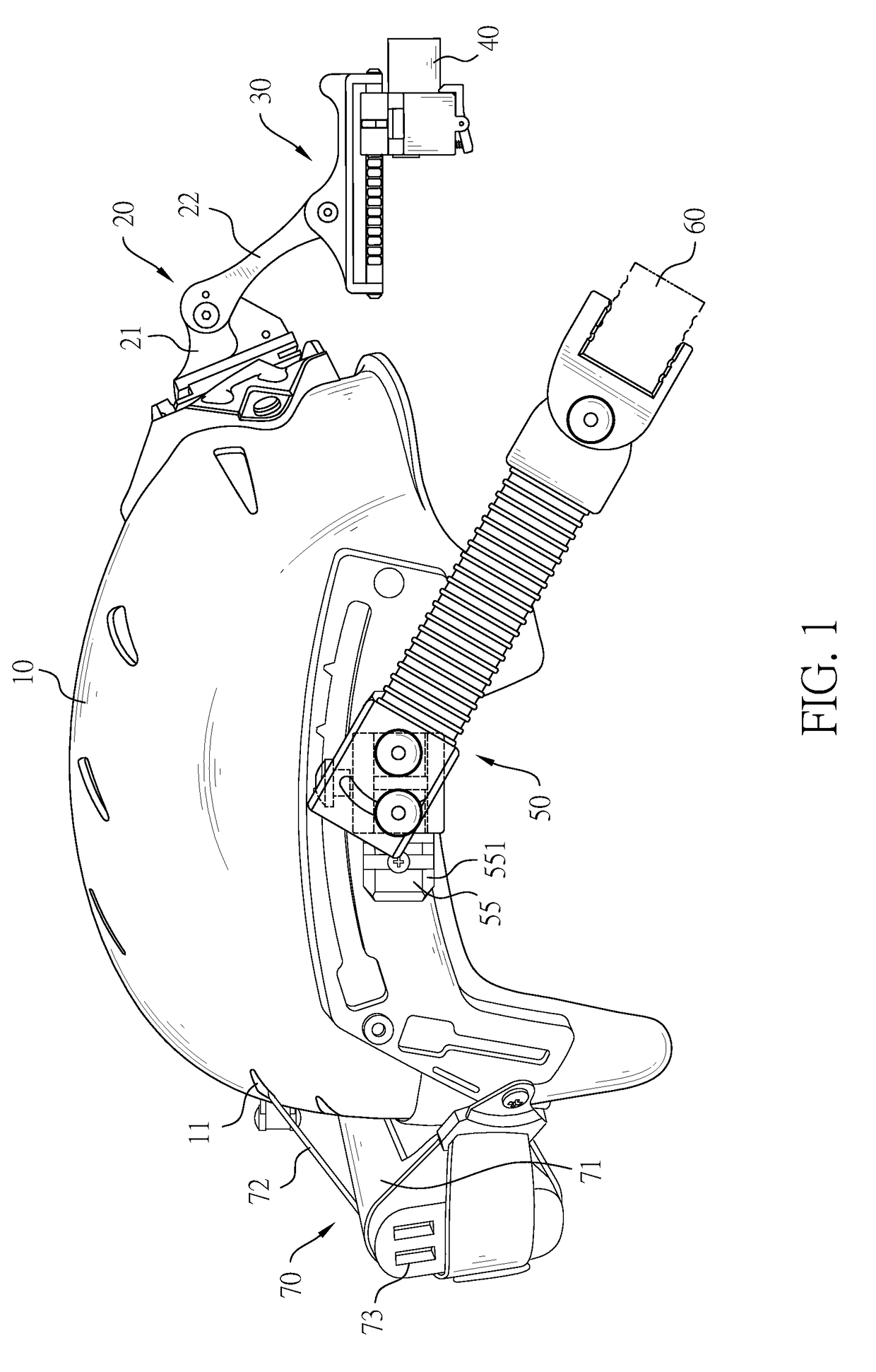
[0026]With reference to FIG. 1, a helmet in accordance with the present invention comprises a cap 10, a turning assembly 20, a fastening device 30, a camera 40, a supporting device 50, and a battery set 70.

[0027]The cap 10 is a hollow shell, is used for covering a user's head and has multiple through holes 11 separately formed through the cap 10.

[0028]With further reference to FIG. 7, the turning assembly 20 is assembled on the cap 10 and has a main base 21, two arms 22, a swing seat 23, and two guiding rods 24.

[0029]The main base 21 is securely mounted on the cap 10, is disposed outside the cap 10, and has two end surfaces, two mounting recesses 211, two recess walls, and two abutting portions 212. One of the end surfaces of the main base 21 is securely attached to the cap 10. The mounting recesses 211 are separately formed in the other end surface of the main base 21. The recess walls are respectively defined in the mounting recesses 211. The abutting portions 212 are respectively...


PUM


Abstract

The helmet has a cap, and a turning assembly and a fastening device assembled on the cap. The helmet is formed as an integral whole and has a simplified and compact structure. A camera is mounted to the fastening device and is held by a lower holder and an upper holder of the turning assembly. A locking panel of the fastening device allows the camera to be easily and quickly mounted onto the cap via the fastening device or removed from the fastening device. With a locking member engaging in or disengaging from one of multiple engaging recesses of a corresponding guiding rod of the turning assembly, a position of the camera relative to the cap can be also easily and quickly adjusted.

Description

CROSS-REFERENCE TO RELATED APPLICATIONS[0001]This application is based upon and claims priority under 35 U.S.C. 119 from Taiwan Patent Application No. 106119887 filed on Jun. 14, 2017, which is hereby specifically incorporated herein by this reference thereto.BACKGROUND OF THE INVENTION1. Field of the Invention[0002]The present invention relates protective equipment worn to protect head, especially to a helmet that is assembled with a variety of equipments.2. Description of the Prior Art(s)[0003]A helmet is worn to protect a user's head from injuries. For instance, a bicycle rider or a motorcycle rider wears the helmet and the helmet can protect the rider's head during impact. Moreover, as for popular outdoor activities, such as extreme sports or shooting sports, a player also has to wear protective equipment including the helmet, so as to prevent the player's head from being injured during fast moving or chasing.[0004]In order to record videos when doing the afore-mentioned outdoor...

Claims


Application Information

Patent Timeline
IPC IPC(8): A42B3/04G03B17/56A45F5/02
CPCA42B3/042G03B17/561A45F5/02A45F2200/0533A45F2005/025A42B3/04F16M13/00
Inventor CHANG, LE-YEN
Owner CHEN TZU CHIANG
Why Eureka
Try Eureka