Fluid conveyance device
a conveyancing device and fluid technology, applied in the direction of positive displacement liquid engine, piezoelectric/electrostrictive/magnetostrictive device, piezoelectric/electrostriction/magnetostriction machine, etc., can solve the problems of difficult implementation of the mechanism for conveying a miniature volume pocket holding fluid, the bulky structure of the pump, and the difficulty of sealing the fluid. achieve the effect of simple and compact structur
- Summary
- Abstract
- Description
- Claims
- Application Information
AI Technical Summary
Benefits of technology
Problems solved by technology
Method used
Image
Examples
first preferred embodiment
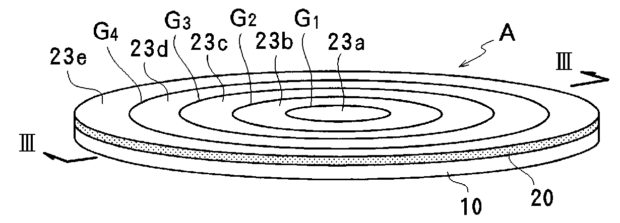
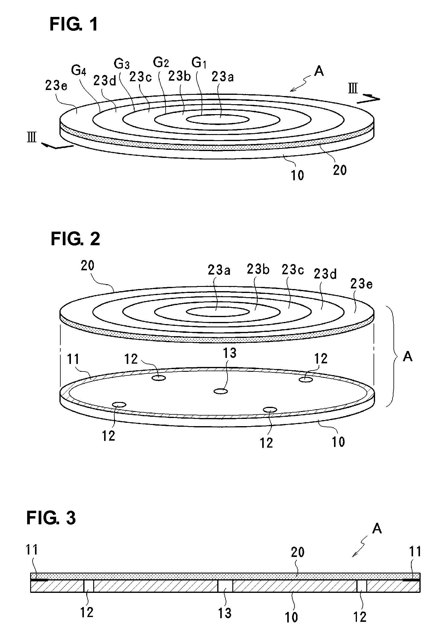
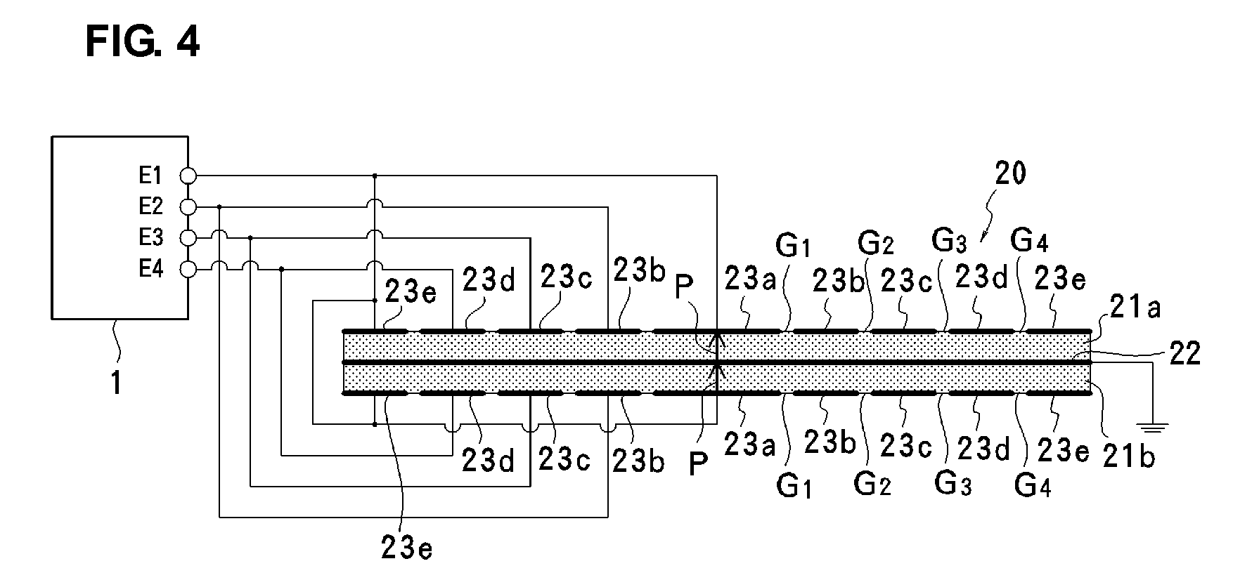
[0046]FIGS. 1-3 illustrate a first preferred embodiment of a fluid conveyance device of the present invention. Here, the fluid conveyance device is preferably used as an air supplying micro pump. FIG. 1 is a perspective view of the micro pump A of the first preferred embodiment, FIG. 2 is an exploded perspective view of the micro pump A, and FIG. 3 is a sectional view taken along line III-III in FIG. 1.
[0047]The micro pump A of the first preferred embodiment includes a substrate 10 defining a fixed plate, and a disk-shaped piezoelectric element 20 arranged in a bendable manner on the substrate 10. An entire or substantially entire outer substantially circular portion of the piezoelectric element 20 is preferably bonded to the piezoelectric element 20 preferably by an adhesive agent 11, for example. In accordance with the first preferred embodiment, the substrate 10 and the piezoelectric element 20 are preferably disks having the same or substantially the same diameter, for example. ...
second preferred embodiment
[0058]FIGS. 12A-14 illustrates a second preferred embodiment of a fluid conveyance device of the present invention. Unlike the first preferred embodiment, the second preferred embodiment includes two different patterns as the segment electrodes of a piezoelectric element 30. With the diameter of the piezoelectric element 30 being 5D, a first electrode pattern includes three concentric substantially circular segment electrodes 32a-32c divided along a diameter D and a diameter 3D as illustrated in FIG. 12A, and a second electrode pattern includes three concentric substantially circular segment electrodes 33a-33c divided along a diameter 2D and a diameter 4D as illustrated in FIG. 12B.
[0059]As illustrated in FIG. 13, two types of segment electrodes 32a-32c and 33a-33c are preferably laminated with piezoelectric layers 31a and 31b interposed therebetween. The segment electrodes 32a at the approximate center are mutually connected to the outermost segment electrodes 32c, and the segment ...
third preferred embodiment
[0063]FIGS. 17-19 illustrate a third preferred embodiment of the fluid conveyance device of the present invention. In accordance with the third preferred embodiment, the electrode patterns of a piezoelectric element 40 are not concentric, but are arranged in a deviated arrangement as illustrated in FIG. 17. More specifically, ring segment electrodes 41b-41e are successively arranged around a central segment electrode 41a in an arrangement that is not centered. A pitch of the gaps G4-G4 defining border lines between the segment electrodes is set to substantially proportional to the square root of a distance to an imaginary straight line O, shown in FIG. 19, outside the piezoelectric element 40. In this preferred embodiment, the imaginary straight line O is x=0 (Y axis in FIG. 18). The border line pitch is preferably set to be about 0.8x0.5, for example, so that the pitch is substantially proportional to the square root of a distance x from the imaginary straight line O. If the diamet...
PUM
 Abstract
Description
Claims
Application Information
 - R&D
- Intellectual Property
- Life Sciences
- Materials
- Tech Scout
- Unparalleled Data Quality
- Higher Quality Content
- 60% Fewer Hallucinations
Browse by: Latest US Patents, China's latest patents, Technical Efficacy Thesaurus, Application Domain, Technology Topic, Popular Technical Reports.
© 2025 PatSnap. All rights reserved.Legal|Privacy policy|Modern Slavery Act Transparency Statement|Sitemap|About US| Contact US: help@patsnap.com


