Method and apparatus for mounting electronic components

a technology for mounting electronic components and electronic components, applied in the field of methods, can solve the problems of large and complicated apparatus structure, and achieve the effect of simple and compact apparatus structure, enhancing speed and flexibility of transfer actions, and contributing to the simple and compact structur

Inactive Publication Date: 2001-07-31
PANASONIC CORP
View PDF21 Cites 34 Cited by
  • Summary
  • Abstract
  • Description
  • Claims
  • Application Information

AI Technical Summary

Benefits of technology

According to the above-described arrangement, the tray which has been transferred to the tray feeding position in the component feeding unit is pulled out by the tray draw-out means by an amount such that the electronic components of desired type are brought to locate on a one-axis transfer line of the transfer mechanism. The transfer mechanism picks up the electronic components by suction and transfers them on to the temporary holder located along the component transfer line. As the temporary holder is capable of holding a plurality of electronic components of which number corresponds to the number of mounting nozzles on the mounting head, several electronic components can be aligned on the temporary holder in the order of mounting operation by repeating the aforementioned transferring operation. The mounting head carries out the mounting operation on to the circuit board by picking up several electronic components at a time from the temporary holder while the transferring of electronic components that are to be mounted next is being effected. Due to the arrangement in which the tray draw-out means controls the amount of pulling out the tray to cause the electronic components to locate on the component transfer line and that the temporary holder is disposed on this component transfer line, the transfer mechanism can be constructed to be movable only along one axis, thus allowing the entire structure of the apparatus to be simple and compact.
The temporary holder may be disposed on the draw-out arm of the tray draw-out means, thereby obviating the need for an extra space for installation, further contributing to the simple and compact structure.
Further, the component feeding unit may have a plurality of tray feeding positions, and the tray draw-out means may be arranged in plurality corresponding to such tray feeding positions, each tray draw-out means including the temporary holder disposed on their respective draw-out arms, whereby transfer locations of the electronic components can be more freely selected, thus enhancing the speed and flexibility of the transferring actions.

Problems solved by technology

For that purpose, it is necessary to provide a transfer mechanism which is capable of picking up components 2 and moving along at least two directions (on X-Y plane) and a temporary holding means on which components are held, causing the entire structure-of the apparatus to be large and complicated.

Method used


Image

  • Method and apparatus for mounting electronic components
  • Method and apparatus for mounting electronic components
  • Method and apparatus for mounting electronic components

Examples


Embodiment Construction

One embodiment of the present invention will be hereinafter described referring to the accompanying drawings. It is to be understood that the following embodiments are merely specific examples of the present invention and are not intended to limit the technical scope thereof.

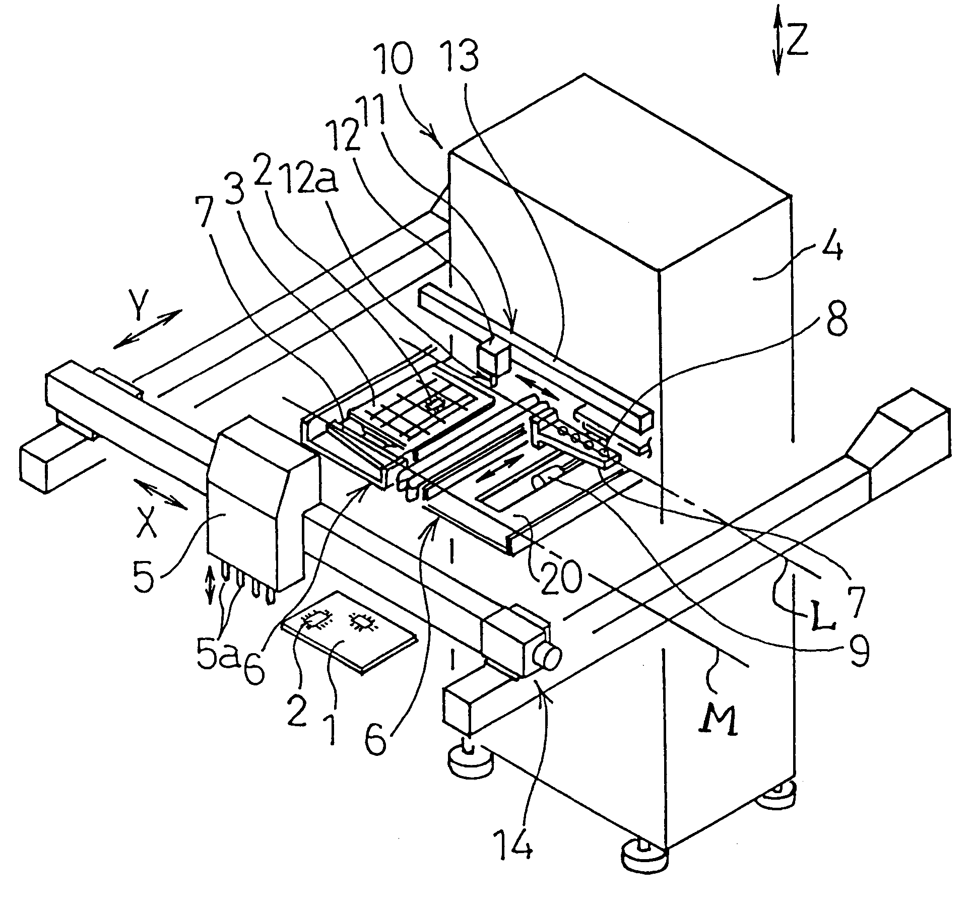
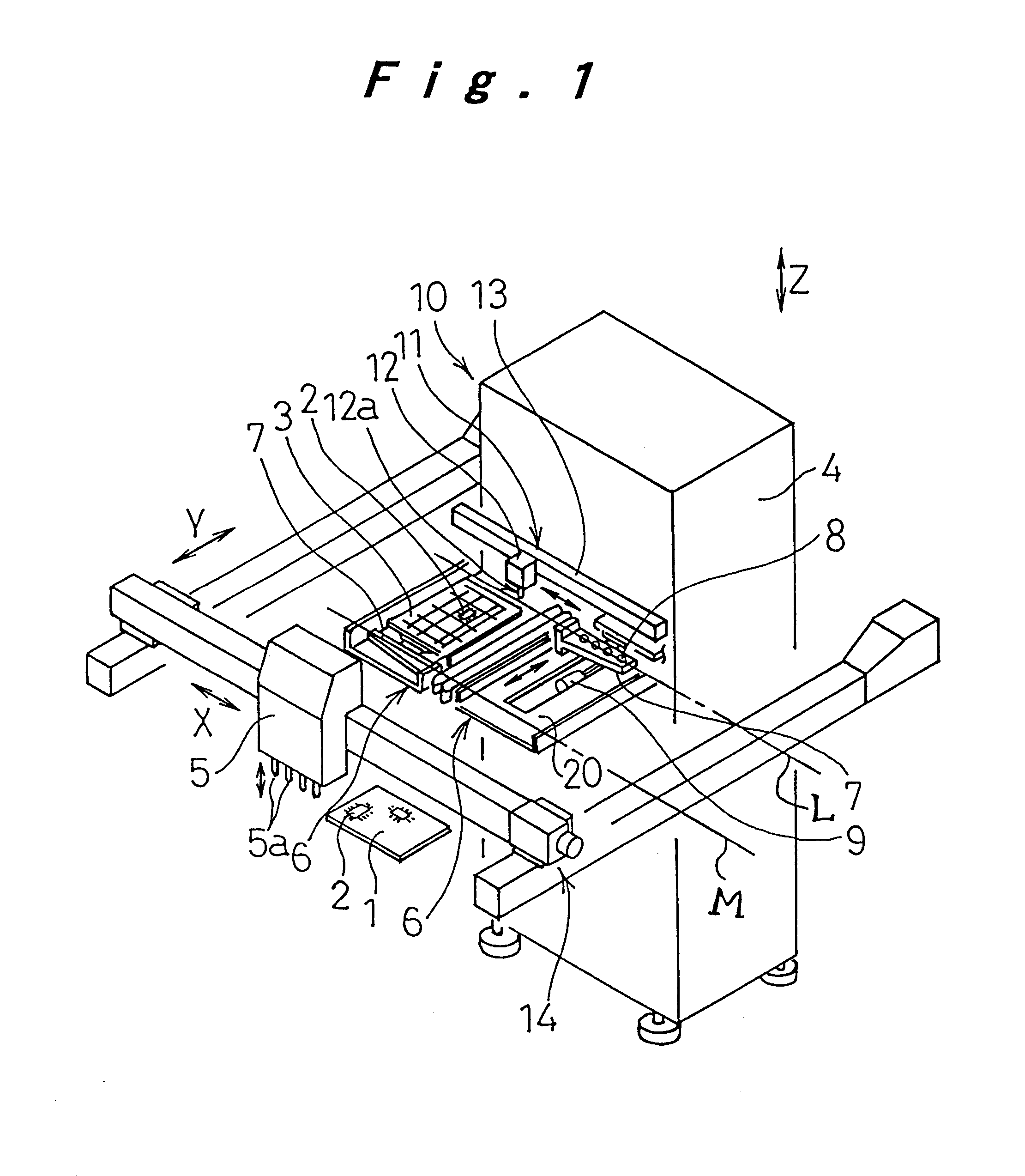
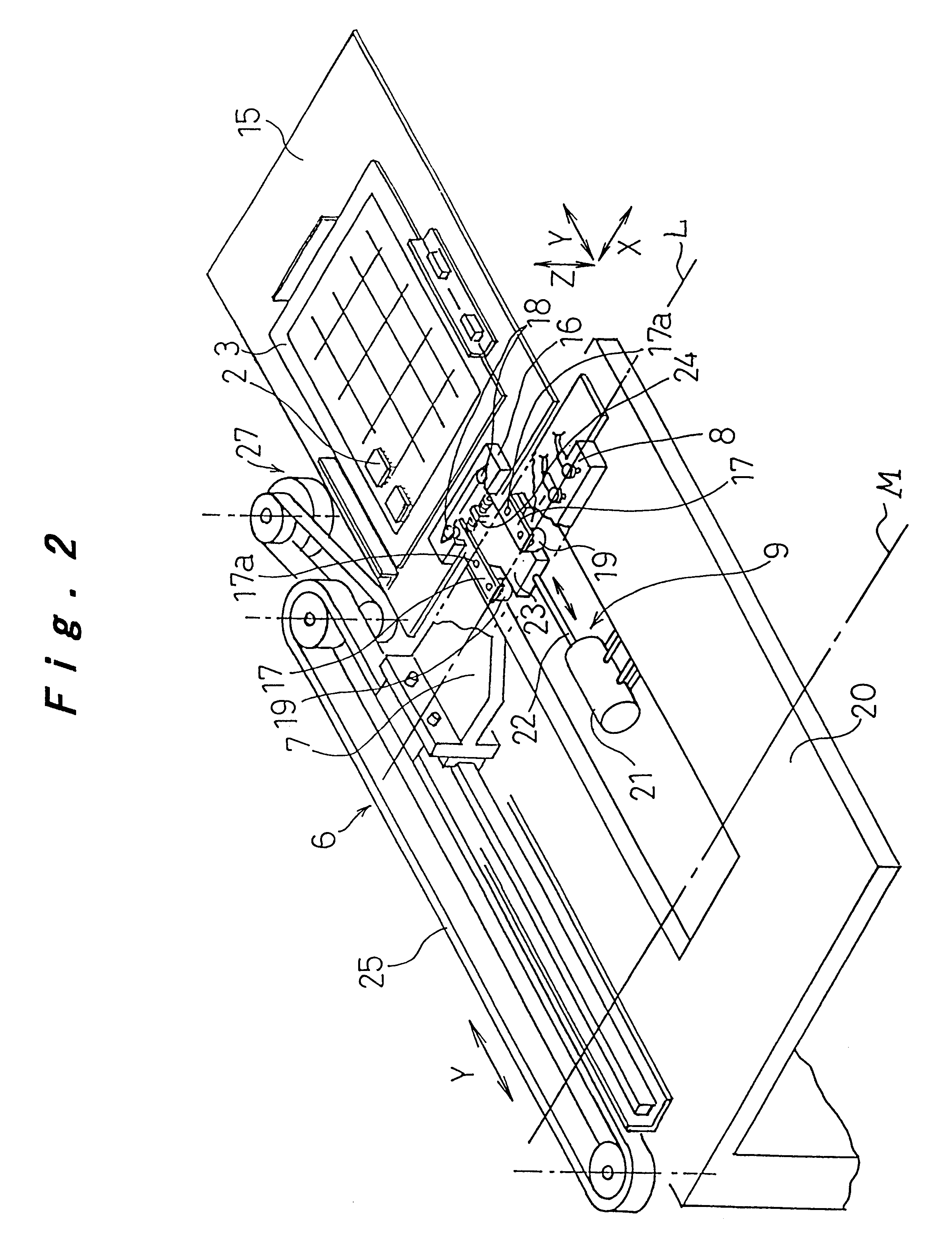
FIG. 1 is a perspective view showing an electronic component mounting apparatus according to one embodiment of the present invention; FIG. 2 is an enlarged perspective view of one of tray draw-out means of the present invention; and FIG. 3 is a perspective view showing the structure of a transfer mechanism of the present invention.

In FIG. 1, reference numeral 10 denotes the electronic component mounting apparatus, which includes a component feeding unit 4, a pair of tray draw-out means 6, a transfer mechanism 11, a mounting head 5, and an X-Y robot 14. Component feeding unit 4 has a pair of tray magazines arranged side by side in which trays or storage members 3 loaded with electronic components 2 are stacked in...


PUM

PropertyMeasurementUnit
anglesaaaaaaaaaa
movementaaaaaaaaaa
sizeaaaaaaaaaa

Abstract

Method and apparatus for mounting electronic components in which components are efficiently fed and transferred for enhancing productivity is provided. Tray draw-out device (6) is disposed at a component feeding unit (4) for pulling out a tray (3) accommodating electronic components (2) from the component feeding unit (4) to a given pick-up position, where the electronic components (2) are transferred by the transfer mechanism (11) on to a temporary holder (8) disposed on a draw-out arm (7) of the tray draw-out device (6). Mounting head (5) has a plurality of mounting nozzles (5a), with which the mounting head (5) picks up several electronic components (2) aligned on the temporary holder (8) at a time and mount them on to a circuit board (1) which has been loaded and located at a prescribed position.

Description

The present invention relates to a method of and an apparatus for mounting electronic components on to a circuit board.One example of a conventional electronic component mounting apparatus is shown in FIG. 6. Electronic component mounting apparatus 30 comprises a loader 39 for carrying in and out a circuit board 1, a component feeding unit 35 which stocks trays 3 loaded with electronic components 2, each tray 3 being fixedly placed on tray shelves stacked in a tray magazine in such a way that the tray 3 accommodating components 2 of desired type is vertically transferred to a proper tray feeding position, a plurality of component feeder reels 32 for supplying electronic components 31 which are stocked in a row on a tape-like member wound around a reel, a mounting head 33 equipped with a suction nozzle 34 which picks up electronic components 2(31) by suction from the component feeding unit 35 or the component feeder reels 32 and mounts them on to the circuit board 1 located at a pres...

Claims


Application Information

Patent Timeline
Patent Type & Authority Patents(United States)
IPC IPC(8): H05K13/04
CPCH05K13/0408H05K13/0413H05K13/0452Y10S29/044Y10T29/53174Y10T29/49139Y10T29/53178Y10T29/53183Y10T29/4913Y10T29/53191H05K13/0409H05K13/041H05K13/085H05K13/04
Inventor KITAMURA, NAOYUKIOKUDA, OSAMUKABESHITA, AKIRATAKEDA, TAKESHI
Owner PANASONIC CORP
Why Eureka
Try Eureka