Power converting appartatus

Active Publication Date: 2013-08-01
MITSUBISHI ELECTRIC CORP
View PDF4 Cites 7 Cited by
  • Summary
  • Abstract
  • Description
  • Claims
  • Application Information

AI Technical Summary

Benefits of technology

The present invention provides a power converting apparatus that operates by PWM control while detecting multiple phase currents. The apparatus has a compact and simple structure and can reliably detect the individual phase currents to obtain the desired output. The control unit calculates the values of the individual phase currents by detecting the currents flowing through the DC source line, and performs PWM control operation to cancel out voltage errors that occur during the current detection period. This results in a reduction in size and simplification of the apparatus structure, especially when applied to a power converting apparatus employing a multiplex configuration involving an increased number of kinds of phase currents.

Problems solved by technology

A problem of this arrangement is therefore an increase in size of the apparatus associated with an increase in manufacturing cost.
A problem of this arrangement is that voltage and current output waveforms can be distorted if the output voltage deviates from a desired voltage.

Method used


Image

  • Power converting appartatus
  • Power converting appartatus
  • Power converting appartatus

Examples


first embodiment

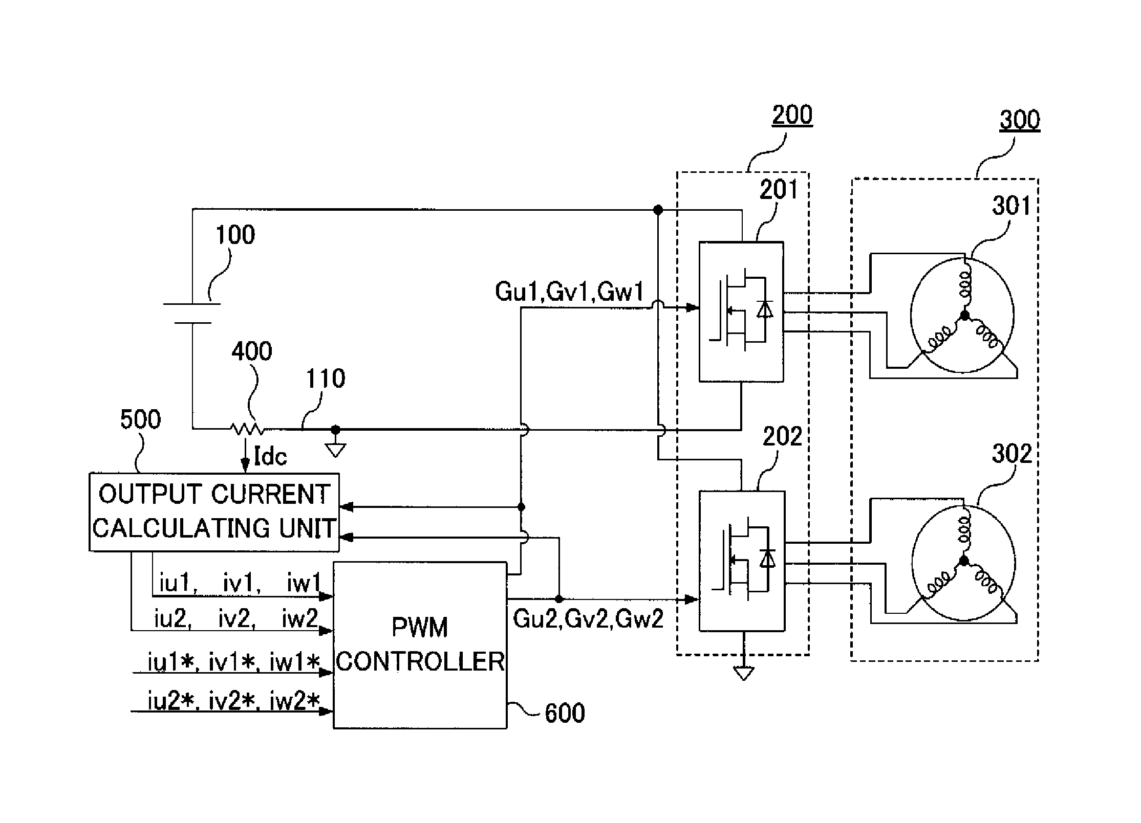
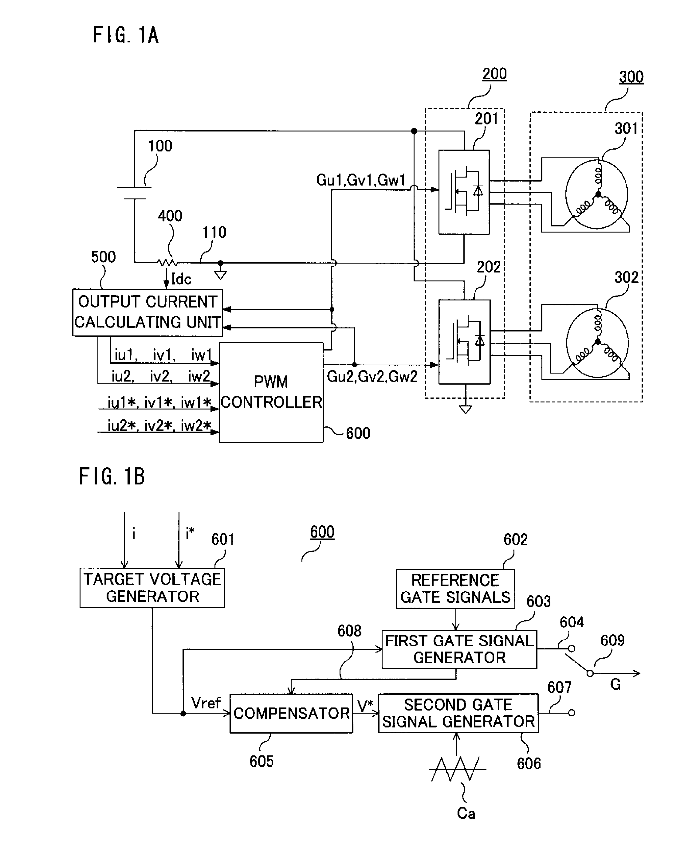
[0023]FIG. 1A is a diagram depicting the configuration of a motor driving system implementing a power converting apparatus according to a first embodiment of the present invention, and FIG. 1B is a control block diagram representing in particular a detailed configuration of a PWM controller 600 depicted in FIG. 1A.

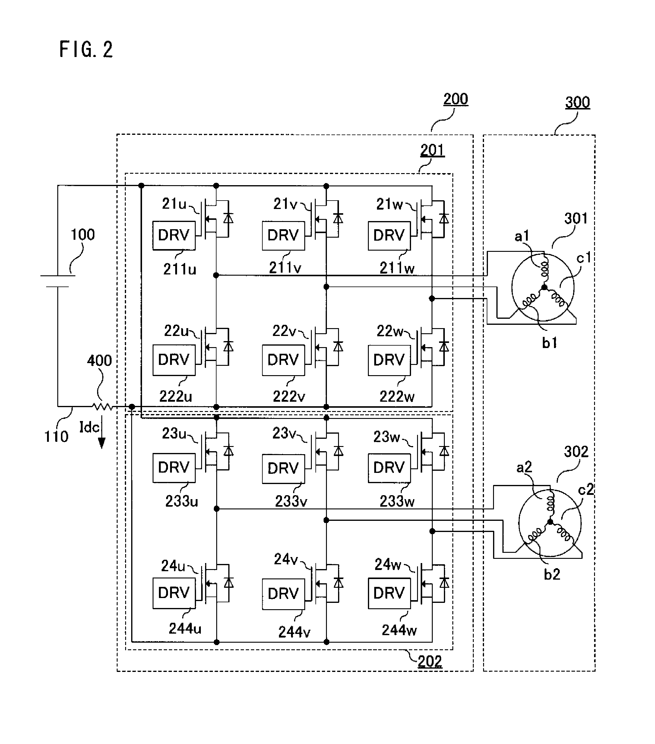
[0024]Configured as depicted in these Figures, the motor driving system converts DC power fed from a DC power source 100 into AC power by means of a multiplex power converter 200 and supplies the AC power to a motor 300. The multiplex power converter 200 includes a first three-phase inverter 201 and a second three-phase inverter 202. These three-phase inverters 201, 202 which are connected in parallel on a DC side together constitute a main circuit unit of the power converting apparatus. For controlling the multiplex power converter 200, the power converting apparatus includes a current detecting device 400 serving as a current detector, an output current calculating unit ...

second embodiment

[0069]FIG. 7 is a diagram depicting the configuration of a motor driving system implementing a power converting apparatus according to a second embodiment of the present invention.

[0070]Configured as depicted in FIG. 7, the motor driving system converts DC power fed from a DC power source 100 into AC power by means of a multiplex power converter 200A and supplies the AC power to a motor 300A. While the foregoing first embodiment employs the multiplex power converter 200 having a duplicate multiplex configuration, the multiplex power converter 200A of the second embodiment constituting a main circuit unit of the power converting apparatus has a quadruple multiplex configuration in which first to fourth three-phase inverters 201-204 are connected in parallel on a DC side. Also, the motor 300A is a 12-phase motor having four pairs of three-phase windings 301-304.

[0071]For controlling the multiplex power converter 200A, the power converting apparatus includes a current detecting device ...

third embodiment

[0089]While the current detection period TA and the current control period TB are set at 0.5Tc and 1.5Tc, respectively, in the foregoing embodiments, the invention is not limited thereto. What is essential is that the control cycle be set at a time period which is an integer multiple of, i.e., one to a few times, the carrier period Tc, the current detection period TA which is synchronized with the carrier period Tc be set at an integer multiple of 0.5Tc, and the current control period TB be set at a time period which is equal to or longer than the current detection period TA.

[0090]A third embodiment described hereunder employs a power converting apparatus which has the same configuration as the foregoing first embodiment depicted in FIGS. 1A and 1B but performs control operation using reference gate signals 602 which differ from those of the first embodiment.

[0091]FIG. 9 is a diagram depicting waveforms for explaining gate signals G (Gu1, Gv1, Gw1, Gu2, Gv2, Gw2) to be used during t...


PUM


Abstract

In a power converting apparatus having a plurality of phases on an AC side and configured to perform conversion between DC power and AC power, a current detector detects currents flowing through a DC source line through which a plurality of phase currents commonly flow. A control unit sets a current detection period and a succeeding current control period in each successive control cycle. Using first gate signals based on reference gate signals for PWM control, the control unit calculates values of the individual phase currents from the first gate signals and the detected currents during the current detection period. Then, during the current control period, the control unit performs PWM control using phase voltage commands generated by correcting phase voltage target values so as to cancel out voltage errors that occur during the current detection period.

Description

BACKGROUND OF THE INVENTION[0001]1. Field of the Invention[0002]The present invention relates to a power converting apparatus for performing conversion between DC power and AC power by using a plurality of semiconductor switching devices and, more particularly, to a power converting apparatus configured to operate by pulse-width modulation (PWM) control operation while detecting a plurality of phase currents.[0003]2. Description of the Background Art[0004]A conventional arrangement for increasing an output of a power converting apparatus is to use a multiplex inverter in which a plurality of three-phase inverters are connected in parallel. This kind of multiplex inverter is provided with three-phase inverters each including three current detectors and operates by PWM control while detecting individual phase currents (refer to Japanese Patent No. 4625147 and Japanese Patent Application Publication No. 2011-131860, for example).[0005]A conventional arrangement for detecting phase curr...

Claims


Application Information

Patent Timeline
IPC IPC(8): H02M7/5395
CPCH02M7/53875H02P27/08Y02T10/644B60L15/007B60L3/0061Y02T10/64
Inventor NAKANO, KOSUKEKOJIMA, TETSUYA
Owner MITSUBISHI ELECTRIC CORP
Why Eureka
Try Eureka