
Tandem conical valve

a conical valve and valve body technology, applied in the field of valves, can solve problems such as complex structures of valves and pipelines, and achieve the effect of large instantaneous resistance, simple and compact valve structure, and improved mechanical properties

Active Publication Date: 2019-05-28
YOU YINSEN
View PDF10 Cites 2 Cited by
  • Summary
  • Abstract
  • Description
  • Claims
  • Application Information

AI Technical Summary

Benefits of technology

[0007]To this end, there is a need to provide a conical valve that avoids or reduces the resistance caused by the pressure of the fluid in the pipeline to the valve switch during the opening or closing phase.
[0029]The conical valve is provided with a coaxial second valve core on the basis of the first valve core in an overlapping manner. Meanwhile, a second valve stem rotating the second valve core is sleeved in the first valve stem to make the valve structure be simple and compact, due to the two-staged valve cores can be rotated separately, the separate-staged opening / closing of the valve is realized, which can solve the problem of larger instantaneous resistance when opening and closing the larger conical valve.

Problems solved by technology

The inventor considers adopting a method of creating a separate bypass to keep both sides of the gate with similar fluid pressure for opening and closing the gate, smaller secondary gate valves are opened and closed after the primary gate valves are opened and closed, but such valves and pipelines are of complex structures.

Method used


Image

  • Tandem conical valve
  • Tandem conical valve
  • Tandem conical valve

Examples


Embodiment Construction

[0038]In order to illustrate the technical content, the structural feature, the achievement purpose and the effect of the technical solution in detail, the following embodiments are described in detail with reference to the accompanying drawings.

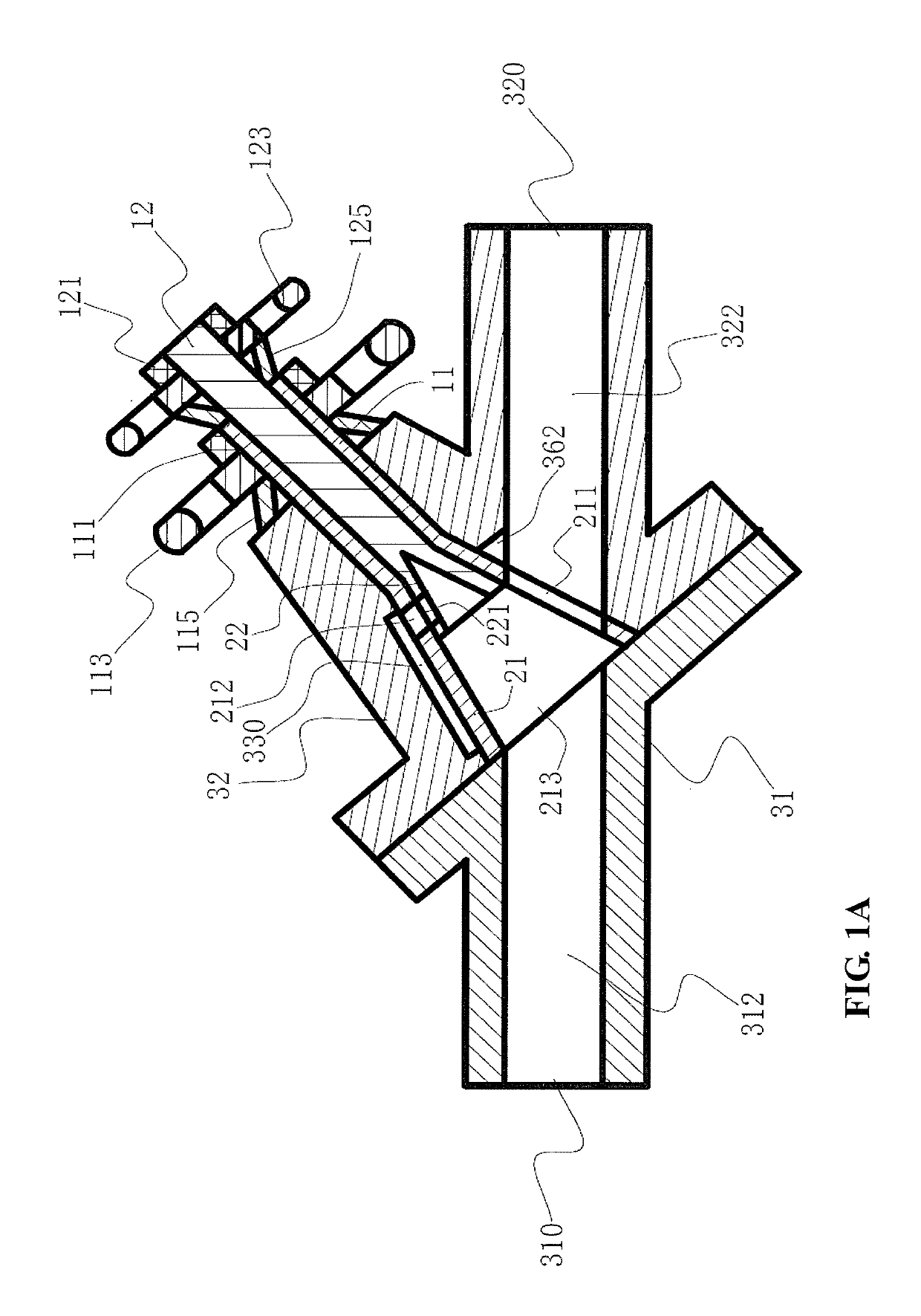
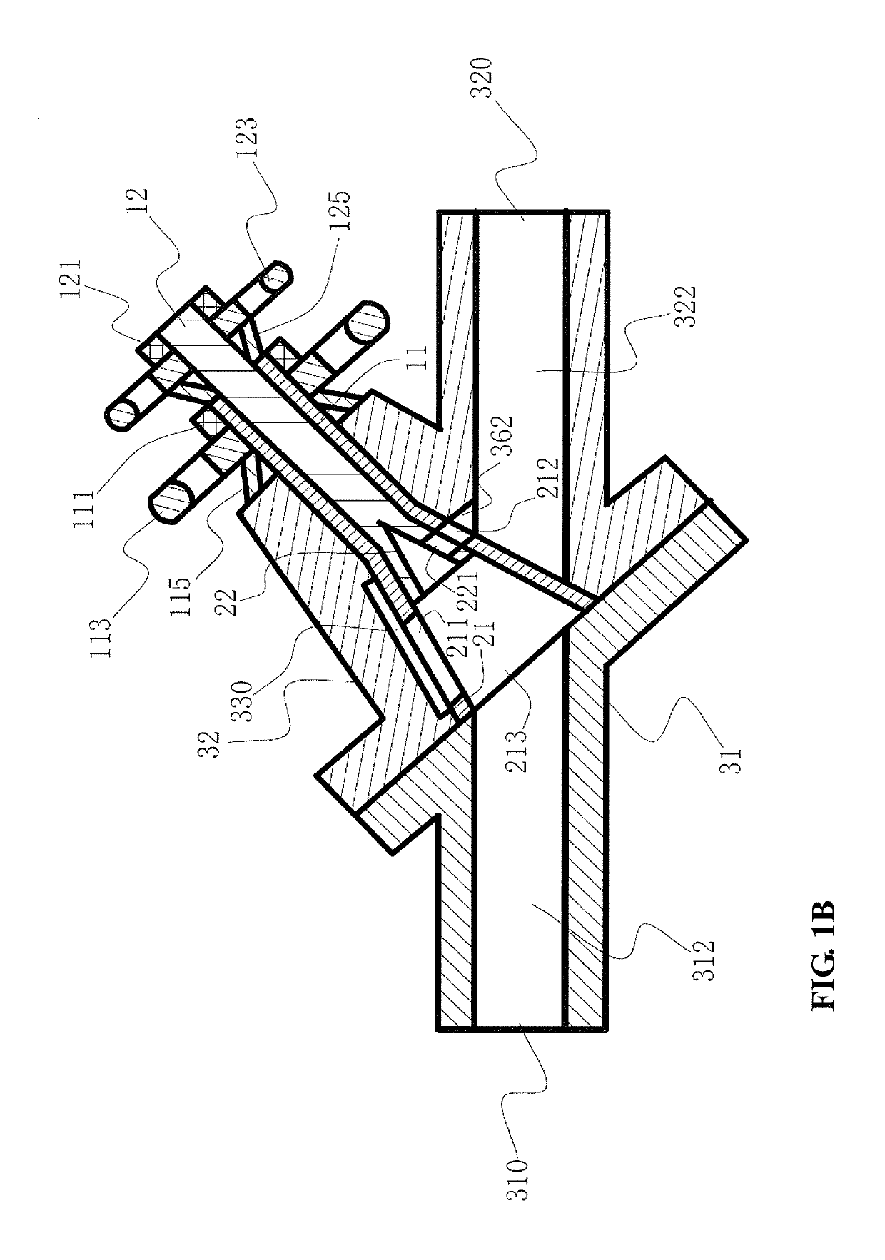
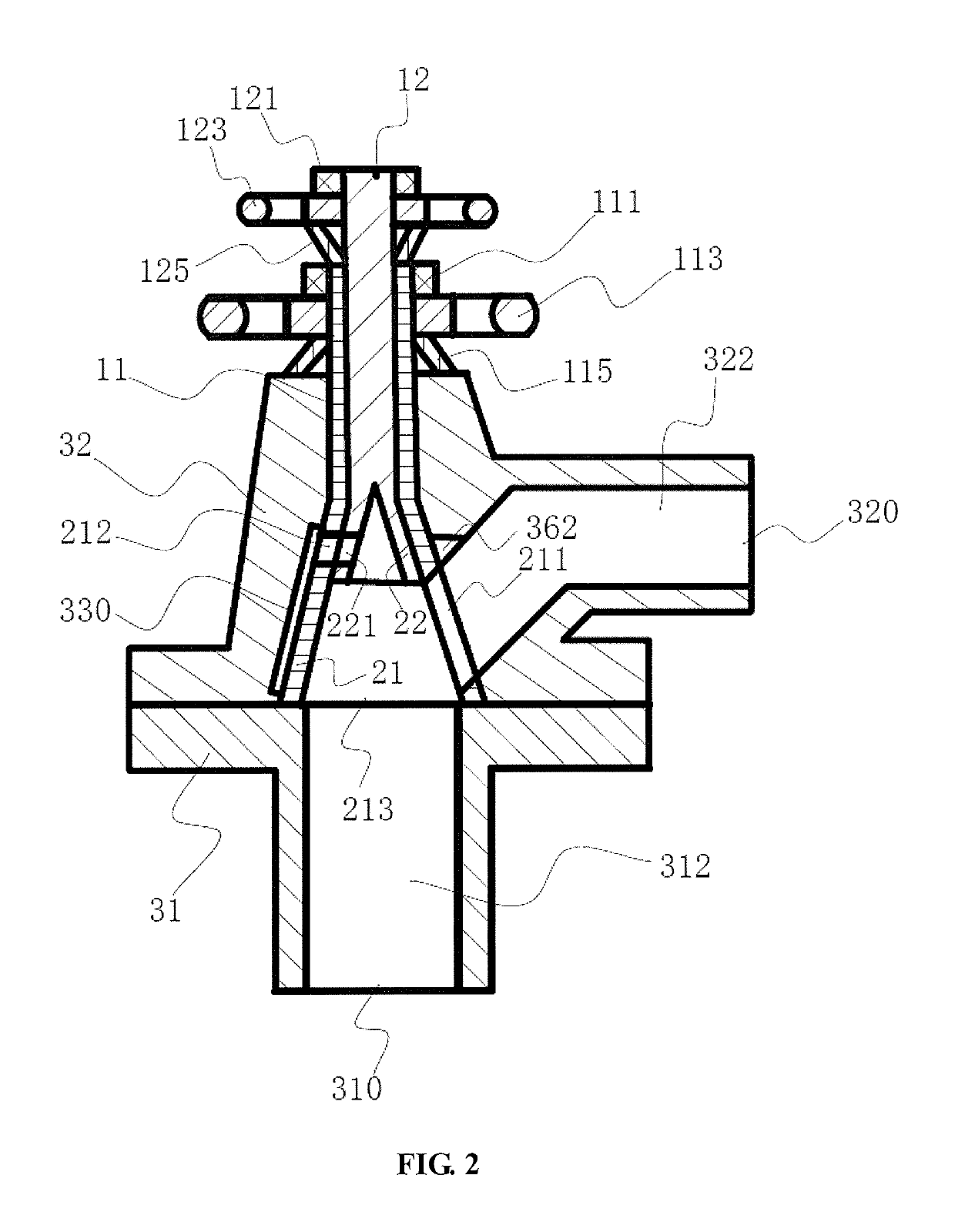
[0039]With reference to FIG. 1A through 3, the embodiment provides a conical valve comprising a valve stem, a valve core and a valve body, the valve stem comprises a first valve stem 11 and a second valve stem 12, and the valve core comprises a first valve core 21 and a second valve core 22;

[0040]the valve body is provided with a fluid inlet and a fluid outlet, the valve body is provided with a valve core cavity for accommodating the first valve core 21 and the second valve core 22, and a valve stem hole for the first valve stem 11 and the second valve stem 12 to pass through, and the valve stem hole penetrates from a surface of the valve body to the valve core cavity.

[0041]The fluid passage between the fluid inlet and the fluid outlet throu...


PUM


Abstract

Provided is a tandem cone valve capable of avoiding or reducing resistance on a valve switch caused by fluid pressure in a pipeline in the opening or closing stage. The cone valve includes valve rods, valve cores and a valve body. The valve cores include a first valve core and a second valve core. The first valve core and the second valve core are coaxially arranged in a valve core cavity. The outer walls of the valve cores are in the shape of cones; the first valve core and the second valve core are stacked one on the other, the first valve core is provided with a first valve core first flow hole and a first valve core second flow hole which penetrate through the inner wall and the outer wall of the first valve core, and the valve core cavity is provided with a valve core cavity flow hole corresponding to the first valve core first flow hole and the first valve core second flow hole. The cone valve is provided with the second valve core stacked coaxially on the base of the first valve core, and the second valve rod driving the second valve core to rotate is arranged in the first valve rod in a sleeved manner, thus the valve is simple and compact in structure; and the two levels of valve cores can each rotate to open / close the valve level by level, thus reducing momentary resistance when opening and closing a large cone valve.

Description

CROSS-REFERENCE TO RELATED APPLICATION[0001]This application is a 371 application of International PCT application serial no. PCT / CN2016 / 102029, filed on Oct. 13, 2016, which claims the priority benefit of China application no. 201510703641.8, filed on Oct. 26, 2015 and the priority benefit of China application no. 201620036398.9, filed on Jan. 25, 2016. The entirety of each of the abovementioned patent applications is hereby incorporated by reference herein and made a part of this specification.TECHNICAL FIELD[0002]The present invention relates to the technical field of valves for conducting or cutting off a fluid passage and regulating fluid flow.BACKGROUND[0003]A valve is a device in a fluid system used to control the direction, pressure, and flow of a fluid, and flowing or stopping the fluid (liquid, gas, powder) in the pipe and equipment and controlling its flow. The valve is a control component in the pipeline fluid delivery system, which is used to change the cross-section of...

Claims


Application Information

Patent Timeline
Patent Type & Authority Patents(United States)
IPC IPC(8): F16K5/02F16K39/06F16K5/10F16K5/08
CPCF16K5/0235F16K5/0207F16K39/06F16K5/08F16K5/10F16K5/0214
Inventor YOU, YINSEN
Owner YOU YINSEN
Learn More