[0011]Therefore, it is an object of the invention to provide a slide rail unit which is simple and compact in structure and easy to assemble and, even when right and left rails are installed to a vehicle floor at an inclination angle different from each other with respect to the longitudinal direction thereof, the right and left rails reliably perform the slide restraint.
[0023]Further, in the slide rail unit of the first aspect of the invention, the
leaf spring member disposed between the operation lever and the lock lever includes the first nip-holding portion and the second nip-holding portion as well as the first engagement portion and the second engagement portion. The first nip-holding portion and the first engagement portion are connected to the lock lever. The first nip-holding portion holds the end portion of the lock lever, and the first engagement portion engages therewith in an anti-disengagement manner. On the other hand, the second nip-holding portion and the second engagement portion are connected to the operation lever. The second nip-holding portion holds the end portion of the operation lever, and the second engagement portion engages therewith in an anti-disengagement manner. That is, the
leaf spring member is connected to the lock lever and the operation lever through a process of hold and engagement. Therefore, so-called one-touch connection is achieved, and also the displacement is reliably prevented after the connection. Therefore, in the slide rail unit of the first aspect of the invention, after connecting one end of the leaf spring member to the lock lever (or operation lever), only by push the other end of the leaf spring member onto the operation lever (or lock lever), the connecting is reliably completed. Consequently, the
assembly work of the slide rail unit is facilitated resulted in an increase of the productivity and a reduction of the manufacturing cost.
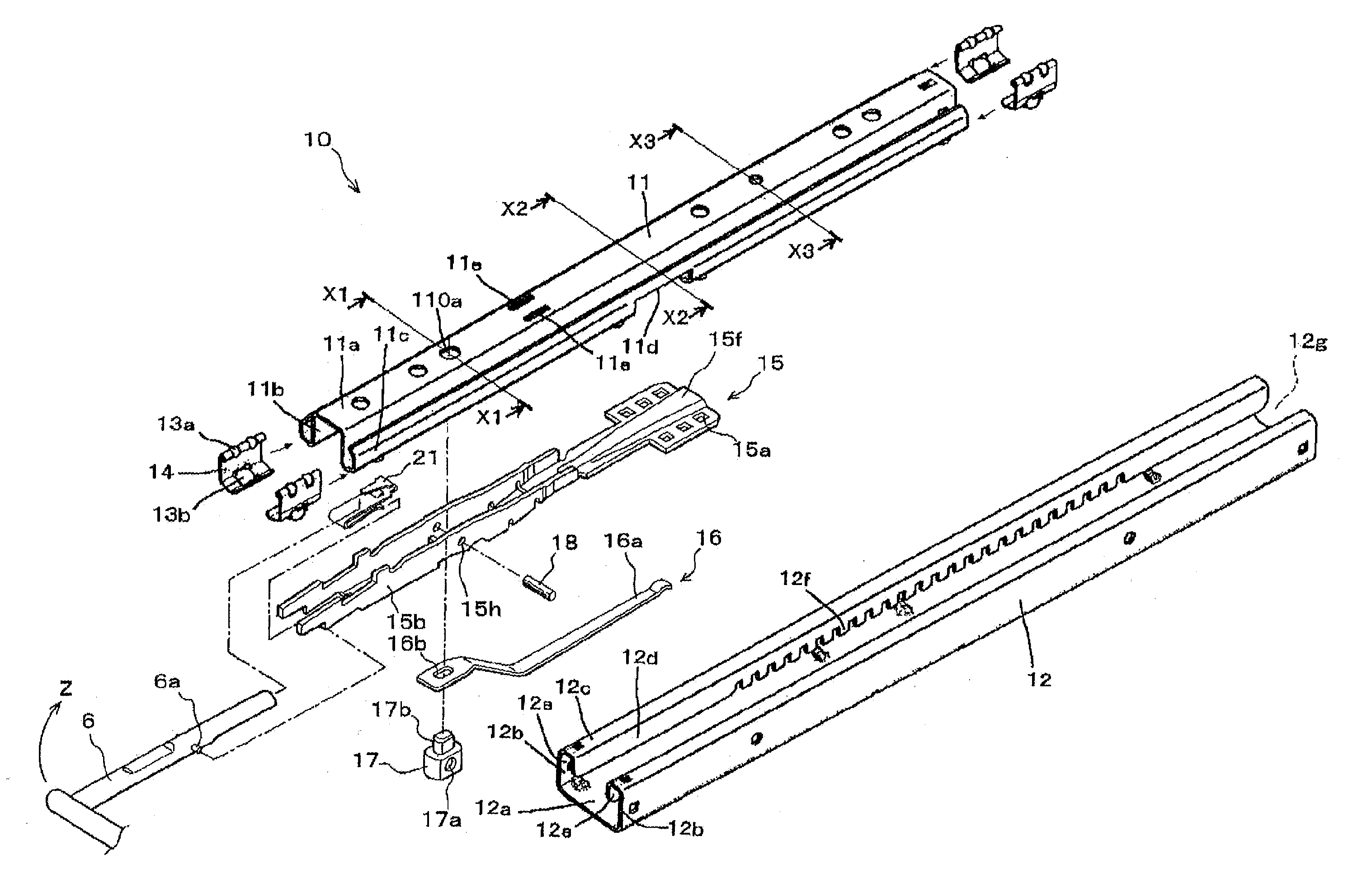
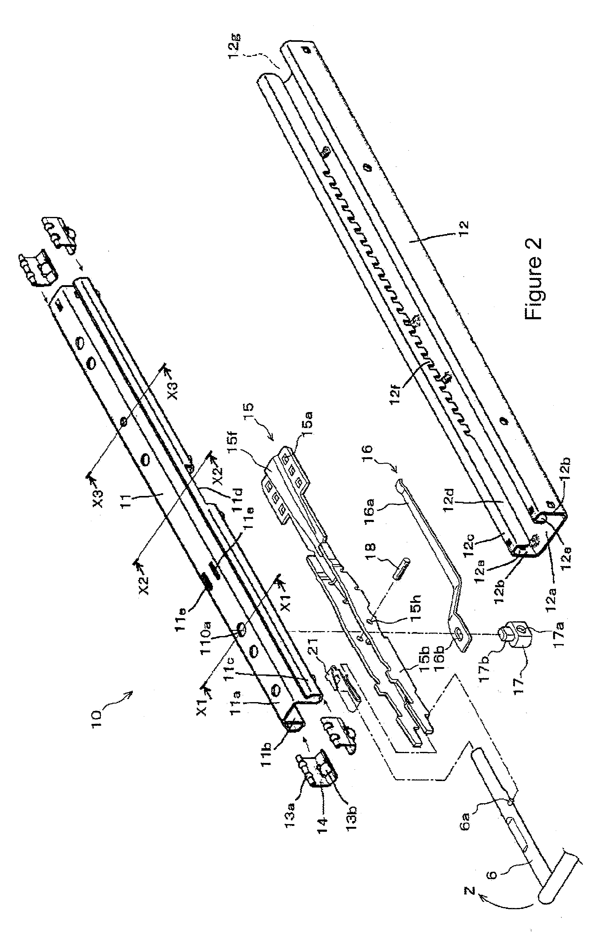
[0024]In the slide rail unit of the second aspect of the invention includes the pair (right and left) of slide rail members. Both end portions of the operation lever, which are inserted from one end portion of the slide rail members, are connected to the lock levers within the slide rail members. Between the operation lever and the respective lock levers, the leaf spring members are disposed, and the leaf spring member imparts a force to the operation lever and the lock lever in a direction to pull the both closer to each other. Therefore, when a load is applied to the operation lever in a direction opposite to the force imparted by the leaf spring member, a force acts on the operation lever to pull back the same toward the lock lever. Therefore, when the pair (right and left) of slide rail members including therein the lock levers connected to the operation lever as described above is installed to a vehicle floor at an inclination angle different from each other with respect to the longitudinal direction thereof, the operation lever tends to part away from the lock lever against the force imparted by the leaf spring member. However, the leaf spring member pulls the operation lever and the lock lever in a direction closer to each other, and thus the connection therebetween is maintained. Therefore, according to the invention of the second aspect, the operation lever and the lock lever are permitted to part away a little from each other while maintaining the state that both are held close to each other. Therefore, even when an error is generated in installation angle between the right and left slide rail members, the error can be absorbed. Therefore, since an unintended force is prevented from being given to one or both of the slide rail members by the operation lever, slide restraint can be reliably achieved with the right and left seat rail members. It should be noted that, according to the second aspect of the invention, an error of installation angle due to deformation of the floor generated at vehicle collision can be also absorbed, and thus the slide restraint can be reliably achieved.
[0026]Therefore, according to the third aspect of the invention, the lock lever is supported at two points by the first nip-holding portion and the first engagement portion. On the other hand, the operation lever is supported at two points by the second nip-holding portion and the second engagement portion. Consequently, the leaf spring member can be connected strongly and stably to the lock lever and the operation lever. Further, according to the third aspect of the invention, since the structure is simple, the leaf spring member can be manufactured easily, and the risk of failure of the slide rail unit can be reduced.
[0027]Furthermore, in the leaf spring member according to the fourth aspect of the invention, both of the end portions to be connected to the lock lever or the operation lever are formed in a configuration identical to each other. Either side of the leaf spring member can be connected to either of the lock lever and operation lever. Therefore, the slide rail unit can be manufactured more easily resulting in an increase of the productivity moreover.
[0028]According to the fifth to eighth aspects of the invention, either one or both of the operation lever and the lock lever are formed with a projection that causes the operation lever and the lock lever to engage with each other. Therefore, when a passenger operates the operation lever at least in a direction to release the slide restraint, the operation lever and the lock lever come into contact with the projection and the leaf spring member at two points. Thus, utilizing the principle of leverage, the lock lever can be reliably rotated in the direction to release the slide restraint.

