Connector with a connection detecting function

Inactive Publication Date: 2010-12-02
SUMITOMO WIRING SYST LTD
View PDF6 Cites 5 Cited by
  • Summary
  • Abstract
  • Description
  • Claims
  • Application Information

AI Technical Summary

Benefits of technology

[0011]The displacing directions of the force multiplying member and the shorting member intersect each other. Thus, the synthetic resin force multiplying member may be damaged by the metallic shorting member if the pressing surface directly contacts the shorting member. However, the pressing surface presses the shorting member via the synthetic resin arm. Accordingly, the shorting member will not damage the synthetic resin pressing surface.
[0012]The force multiplying member preferably has a lock that engages the arm separated from the pressing surface when the first and second housings are connected completely. The engagement of the arm and the lock prevents displacement of the force multiplying member.

Problems solved by technology

Foreign matter could intrude between the two detection terminals and could short the two detection terminals, thereby err

Method used


Image

  • Connector with a connection detecting function
  • Connector with a connection detecting function
  • Connector with a connection detecting function

Examples


Example

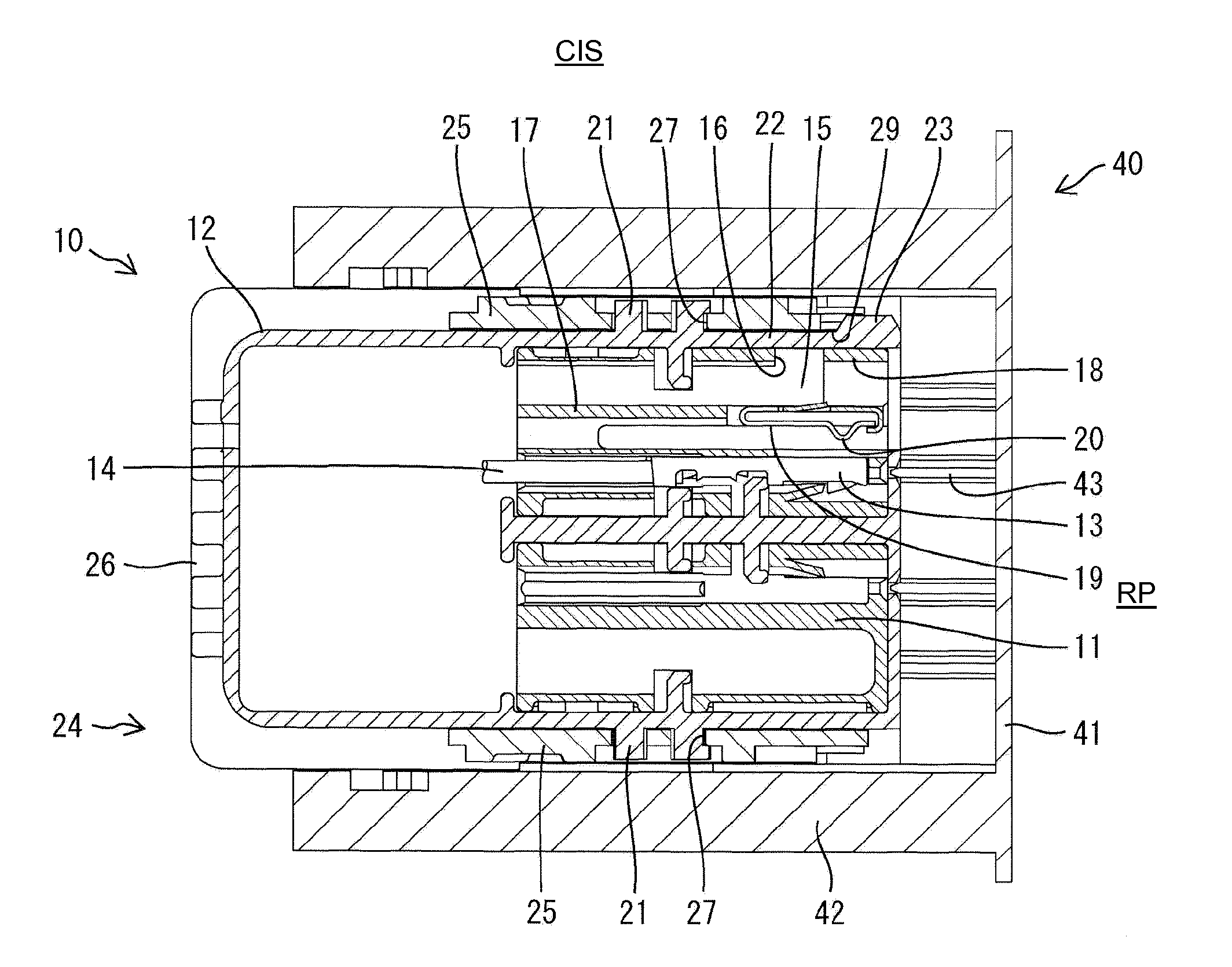
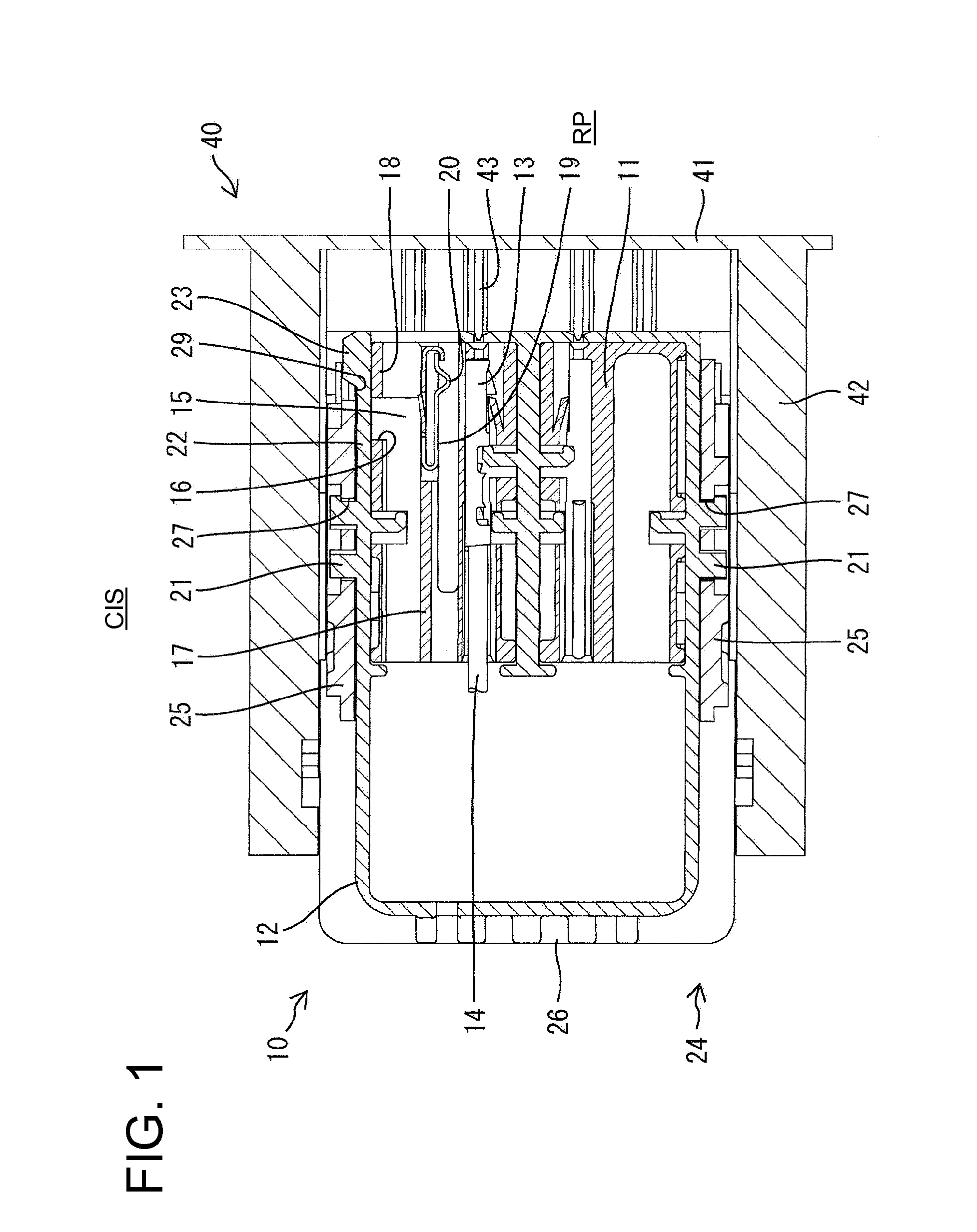
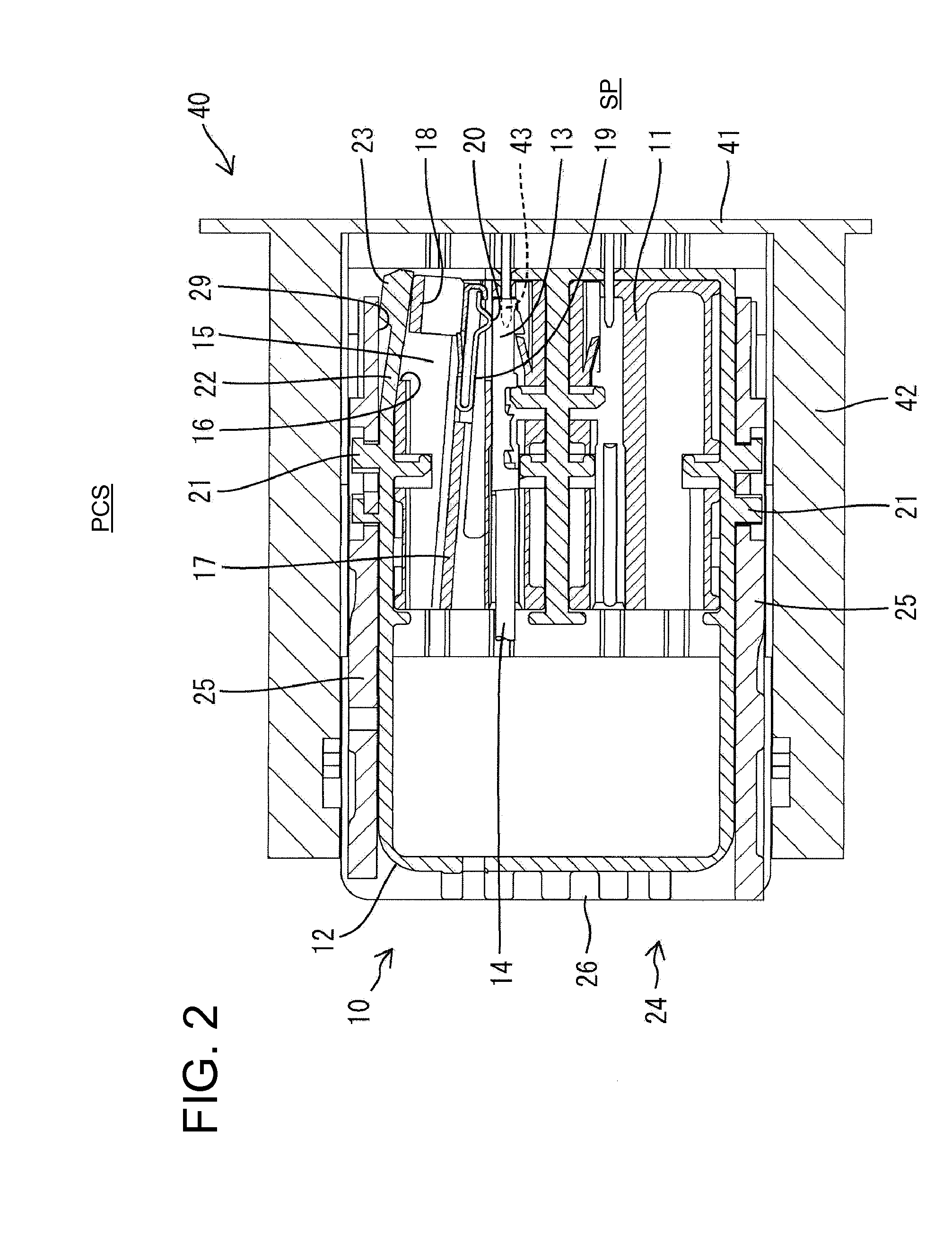
[0025]A connector in accordance with the invention is provided with first and second housings identified respectively by the numerals 10 and 40 in FIGS. 1 to 9. The first and second housing 10 and 40 are connectable with each other and the connector has a function of detecting a connected state of the two housings 10, 40.

[0026]The first housing 10 is formed by assembling two housing main bodies 11 made e.g. of synthetic resin and a wire cover 12 made e.g. of synthetic resin. The housing main bodies 11 are substantially block shaped and are arranged substantially adjacent and one above the other in the wire cover 12. Two female detection terminals 13 and a plurality of female terminal fittings (not shown) are accommodated in the housing main bodies 11. Wires 14 are connected with the respective detection terminals 13 and the female terminal fittings, and parts of these wires 14 exposed from the rear wire drawing surfaces of the housing main bodies 11 are bent laterally at an angle of...


PUM


Abstract

First and second connector housings (10, 40) are connected by displacing a force multiplying member (24). The first housing (10) includes a pair of detection terminals (13) and a shorting member (19). The shorting member (19) is displaced between a shorting position where the detection terminals (13) are shorted and a releasing position where the detection terminals (13) are released from a shorted state. The force multiplying member (24) includes a pressing surface (29) that is parallel to a displacing direction of the force multiplying member (24). The pressing surface (29) displaces the shorting member (19) to the shorting position in a partly connected state where the two housings (10, 40) have not reached a completely connected state while displacing the shorting member (19) to the releasing position when the two housings (10, 40) reach the completely connected state.

Description

BACKGROUND OF THE INVENTION[0001]1. Field of the Invention[0002]The invention relates to a connector with a connection detecting function.[0003]2. Description of the Related Art[0004]U.S. Pat. No. 7,488,197 discloses a connector that can detect whether connector housings are connected completely. This connector has a lock arm that resiliently deforms and pushes a first detection terminal away from a second detection terminal while the housings are being connected (partly connected state). The lock arm resiliently returns when the two housings reach a completely connected state. As a result, the first detection terminal also resiliently returns into contact with the second detection terminal. Thus, the connector detects whether the two housings are connected completely or partly based on whether the first and second detection terminals are in contact.[0005]Foreign matter can intrude between the two detection terminals of the above-described connector and can short the two detection t...

Claims


Application Information

Patent Timeline
IPC IPC(8): H01R31/08
CPCH01R13/62944H01R13/7031
Inventor TONOSAKI, TAKASHI
Owner SUMITOMO WIRING SYST LTD
Why Eureka
Try Eureka