Bearing arrangement

Inactive Publication Date: 2005-03-01
RENISHAW PLC
View PDF21 Cites 6 Cited by
  • Summary
  • Abstract
  • Description
  • Claims
  • Application Information

AI Technical Summary

Benefits of technology

According to one aspect of the present invention there is provided a bearing arrangement comprising:two bearing assemblies each located on an axis;each bearing assembly comprising two parts in contact during their relative rotation;at eac

Problems solved by technology

More complicated bearings have rolling contact, for example ball race or roller sets.
However these bearings need to be manufactured in an accurate manner and are consequently expensive.
This

Method used


Image

  • Bearing arrangement
  • Bearing arrangement
  • Bearing arrangement

Examples


Example

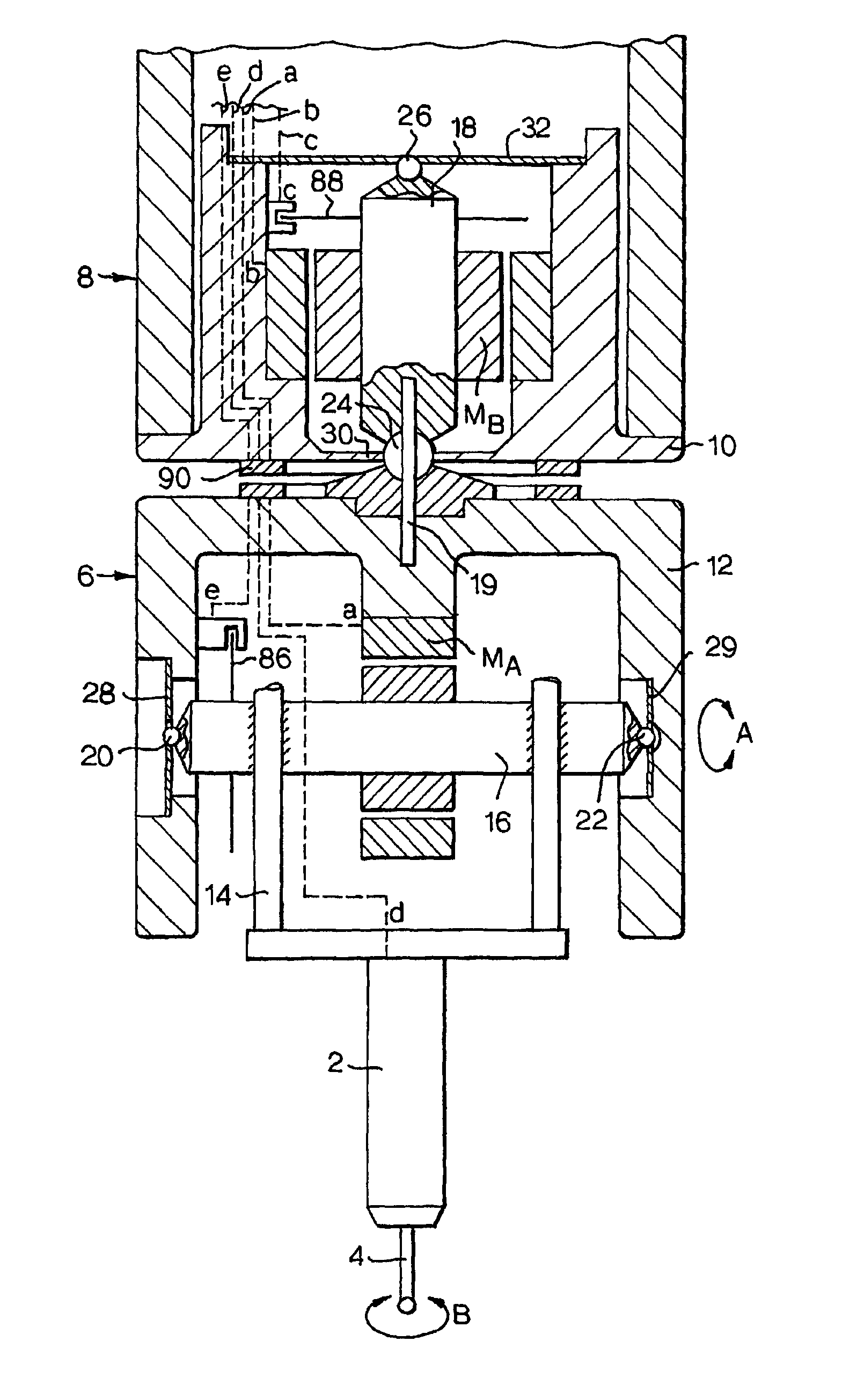
Referring to FIG. 1 there is shown a probe 2 having a stylus 4 for contact with an item to be measured. Conventionally, in use, the quill 8 of a CMM will be moved in any of the three orthogonal axes until the stylus 4 touches an item. The position of the quill 8 with respect to the three axes is then used to determine dimensions of the item.

In addition to the three axes, a probe head 6, attached to the quill 8 between the quill and the probe has a wrist configuration which adds two rotational axes of movement to the probe—rotation “AA” in a vertical plane and rotation “B” in a horizontal plane. Motors MA and MB provide the torque for the rotation in the two axes, so measurements may be taken with or without moving the quill 8, by moving the probe head 6.

Articulation of the head allows more complex movements of the probe, for example to measure the roundness of a bore along its length by moving the stylus in a helical path around the bore. The position of the stylus can be calculated...


PUM


Abstract

A bearing arrangement for an articulatable support (6) comprises bearing assemblies (20/28, 22/29, 24/30 and 26/32). In one embodiment the assemblies comprise a ball (20, 22, 24, 26) and aperture (40 FIG. 2) having sliding contact at discrete areas (36) during relative rotation. In another embodiment the sliding contact may be formed at a ball (20,22,24,26) and a plastics e.g. P.T.F.E. support (84, 85 FIGS. 10 and 11). Resilient displacement of the bearing contact along a rotational axis (A and B) is provided by planar spring supports (28, 32) and rigid support is provided by supports (29 and 30).

Description

BACKGROUND OF THE INVENTION1. Field of the InventionThe present invention relates to a bearing arrangement, particularly but not exclusively in the field of precision bearings for example for measurement apparatus having articulated wrist parts.2. Description of Related ArtPrecision bearings of many forms are known. The simplest rely on the sliding contact to transfer loadings. More complicated bearings have rolling contact, for example ball race or roller sets. Rolling contact is preferred for high loadings, high rotational speeds and long bearing life. However these bearings need to be manufactured in an accurate manner and are consequently expensive. Where thin section parts are used they tend to take up the shape of the housing to which they are fitted. As a consequence, their housings too must be accurately made if good accuracy of movement is to be maintained.Sliding contact bearings may be used for precision bearings, for example watch bearings. Watch bearings, and similar, a...

Claims


Application Information

Patent Timeline
IPC IPC(8): F16C23/00F16C27/00F16C27/02F16C23/04F16C17/04F16C17/00F16C17/08F16C17/10G01D11/02G01D11/00F16C11/06G01B21/00G01B5/012G01B7/00
CPCF16C17/08F16C17/10F16C23/04F16C25/04G01B7/001G01D11/02G01B5/012F16C2370/00
Inventor HUNTER, STEPHEN PAULREEVE, MICHAEL ROBERT JOHNMCMURTRY, DAVID ROBERTSDERRICK, HUGO GEORGE
Owner RENISHAW PLC
Why Eureka
Try Eureka