Improved upward and downward compression mechanism of keyhole machine tool

A technology of pressing structure and machine tool, applied in the direction of cloth pressing mechanism, sewing machine components, textiles and papermaking, etc., can solve the problems of extremely high requirements of assemblers, difficult to achieve good results, difficult adjustment, etc., to reduce assembly requirements and Debugging difficulty, improving assembly and debugging efficiency, and good effect of pressing and positioning

Inactive Publication Date: 2012-02-22
SHANGHAI WEISHI MACHINERY
View PDF6 Cites 6 Cited by
  • Summary
  • Abstract
  • Description
  • Claims
  • Application Information

AI Technical Summary

Problems solved by technology

At present, customers have put forward very high requirements on the straightness of the buttonhole machine, and some customers have even proposed that the straightness should be kept within 0.25mm, and the requirements will become higher and higher in the future. Obviously, the existing buttonhole machine tools Straightness is difficult to achieve;
[0006] The second is that the spinning type upper and lower compression mechanism has relatively high requirements on the precision of the rotation angle of the compression plate, the installation structure of the compression plate is also very complicated, the debugging is also extremely cumbersome, and the assembly is very difficult, which not only requires extremely high requirements for the assembly workers , and greatly strengthened the work intensity of the assembly worke

Method used


Image

  • Improved upward and downward compression mechanism of keyhole machine tool
  • Improved upward and downward compression mechanism of keyhole machine tool
  • Improved upward and downward compression mechanism of keyhole machine tool

Examples


Example Embodiment

[0026] The present invention will be further described below in conjunction with the drawings.

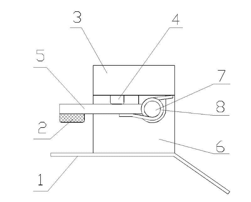
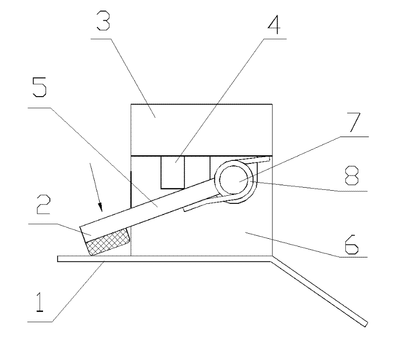
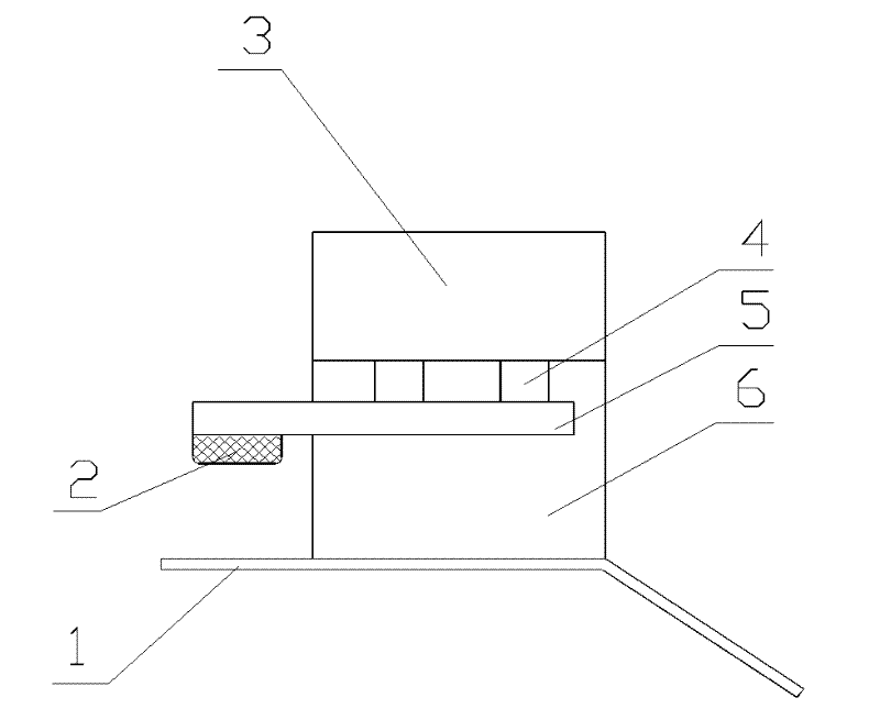
[0027] Figure 1~2 Among them, the structure of the existing upper and lower pressing mechanism is: the lower part is a horizontally fixed support plate 1, the upper part is a rectangular pressing plate 5, and one side of the pressing plate 5 is installed on the upper and lower pressing mechanism through a rotating shaft 7. On the support 6, a torsion spring 8 is arranged between the pressing plate 5 and the rotating shaft 7, and a cylinder 3 is arranged above the swing arm side of the pressing plate 5, and the cylinder piston rod 4 is pressed down against the pressing plate 5. When clamping is required, the piston rod 4 of the cylinder 3 extends downwards, pushing the pressing plate 5 to rotate the arm side and press it down to compress the cloth that needs to be opened, such as figure 2 As shown; when the fabric needs to be loosened, the cylinder piston rod 4 returns upwards, the co...


PUM


Abstract

The invention discloses an improved upward and downward compression mechanism of a keyhole machine tool. An upward and downward compression structure of the keyhole machine tool comprises a retainer plate of which the lower part is fixed horizontally and a compression plate of which the upper side can be opened/closed; and the compression plate is horizontal, and moves vertically up and down in horizontal state under the driving action of a cylinder. When the upward and downward compression structure is pressed down vertically, the problem of displacement of cloth caused by shearing force of a rotary extrusion upward and downward compression structure in the conventional product is solved, the linearity of a shirt top fly keyhole is increased greatly, and the attractiveness of a shirt top fly is ensured; compared with the conventional rotary extrusion upward and downward compression structure, the vertically-pressed upward and downward compression structure has the advantages: the mechanical structure is simplified greatly, the assembling difficulty and debugging difficulty are lowered greatly, the mechanical assembling efficiency is increased, and the maintenance cost of a customer is lowered; and due to the adoption of the vertically-pressed upward and downward compression structure, a sufficient stress surface is ensured during compression of cloth is ensured, the stress is more uniform, and the compression effect is better.

Description

technical field [0001] The invention relates to a buttonhole machine tool for shirt placket buttonholes, in particular to a pressing and positioning structure. Background technique [0002] At present, the existing automatic high-speed keyhole machine tools generally adopt the idea of ​​rotating and pressing: [0003] In the process of opening the buttonhole of the shirt placket, the cloth is repeatedly compressed, transferred and released by multiple upper and lower pressing mechanisms. The structure of the existing upper and lower pressing mechanisms is: the lower part is a horizontally fixed rectangular support plate, and the upper part is a rectangular pressing Tightening plate, one side of the pressing plate is installed on the upper and lower pressing mechanism through a rotating shaft, a torsion spring is arranged between the pressing plate and the rotating shaft, and a cylinder is arranged above the side of the pressing plate’s swing arm, and the piston rod of the cy...

Claims


Application Information

Patent Timeline
IPC IPC(8): D05B29/00D05B29/02
Inventor 吕立毅柴国宣王国顺黄小伟狄金刚
Owner SHANGHAI WEISHI MACHINERY
Why Eureka
Try Eureka