Suspension type suction filtration forming method and suction filtration forming device for plant fiber molding forming

A technology of suction filtration molding and molding molding, which is applied in the direction of textiles and papermaking, etc. It can solve problems such as wet billet tearing, production troubles, and large mold clamping errors, achieve stable up and down movement or positioning, reduce servo motor load, and fast The effect of entering or exiting

Pending Publication Date: 2019-12-27
EURASIA LIGHT IND EQUIP MFR +1
View PDF0 Cites 4 Cited by
  • Summary
  • Abstract
  • Description
  • Claims
  • Application Information

AI Technical Summary

Problems solved by technology

[0004] 1. The up and down movement of the wet billet transfer mold is driven by an oil cylinder. When the piston seal ring of the oil cylinder is worn out, the oil cylinder will leak internally, causing the suction filter forming mold to slide out of control, and the wear of the piston seal ring during the working process is inevitable. Yes, so this has brought a lot of trouble to the production and so far the industry has not been able to solve it
[0005] 2. The wet billet transfer mold cannot be accurately clamped with the suction filter forming mold, and the mold clamping error is large each time, often causing the wet billet to be torn, or the wet billet cannot be transferred to the suction filter forming mold for normal transfer
[0006] 3. When the wet billet transfer mold is clamped with the suction filter forming mold, the impact is too large
[0007] 4. When the wet billet transfer mold transfers the wet billet to the hot-pressing mold, the relative distance between the moisture-absorbing billet transfer die and the hot-pressing die cannot be controlled due to stroke overshoot, and the fibers around the wet billet are caused when the wet billet is transferred. Splashing outside the cavity of the hot-pressing mold produces a lot of burrs, and the fibers splashed on the hot-pressing mold become coke and pollute the hot-pressing mold because they cannot be removed in time
[0008] 5. The oil cylinder pushes the wet billet transfer mold to crawl when it moves up and down. The movement often shakes and is very unstable. After the seal of the cylinder piston rod is damaged, the hydraulic oil in the cylinder often contaminates the slurry
[0009] 6. The up and down movement speed of the wet billet transfer mold is slow, while the up and down movement distance of the suction filter forming mold is often very long, which greatly affects the output

Method used


Image

  • Suspension type suction filtration forming method and suction filtration forming device for plant fiber molding forming
  • Suspension type suction filtration forming method and suction filtration forming device for plant fiber molding forming
  • Suspension type suction filtration forming method and suction filtration forming device for plant fiber molding forming

Examples


Embodiment

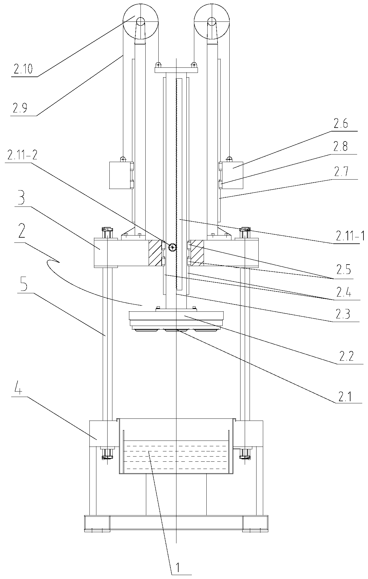
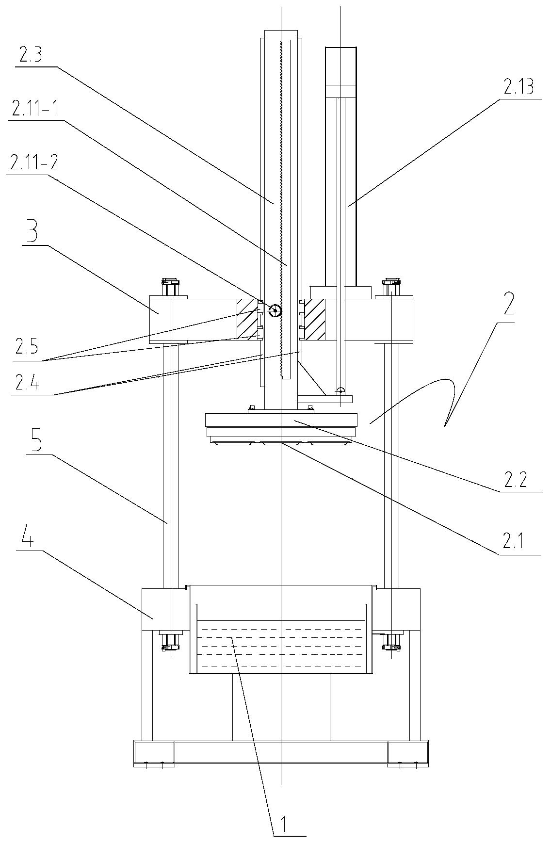
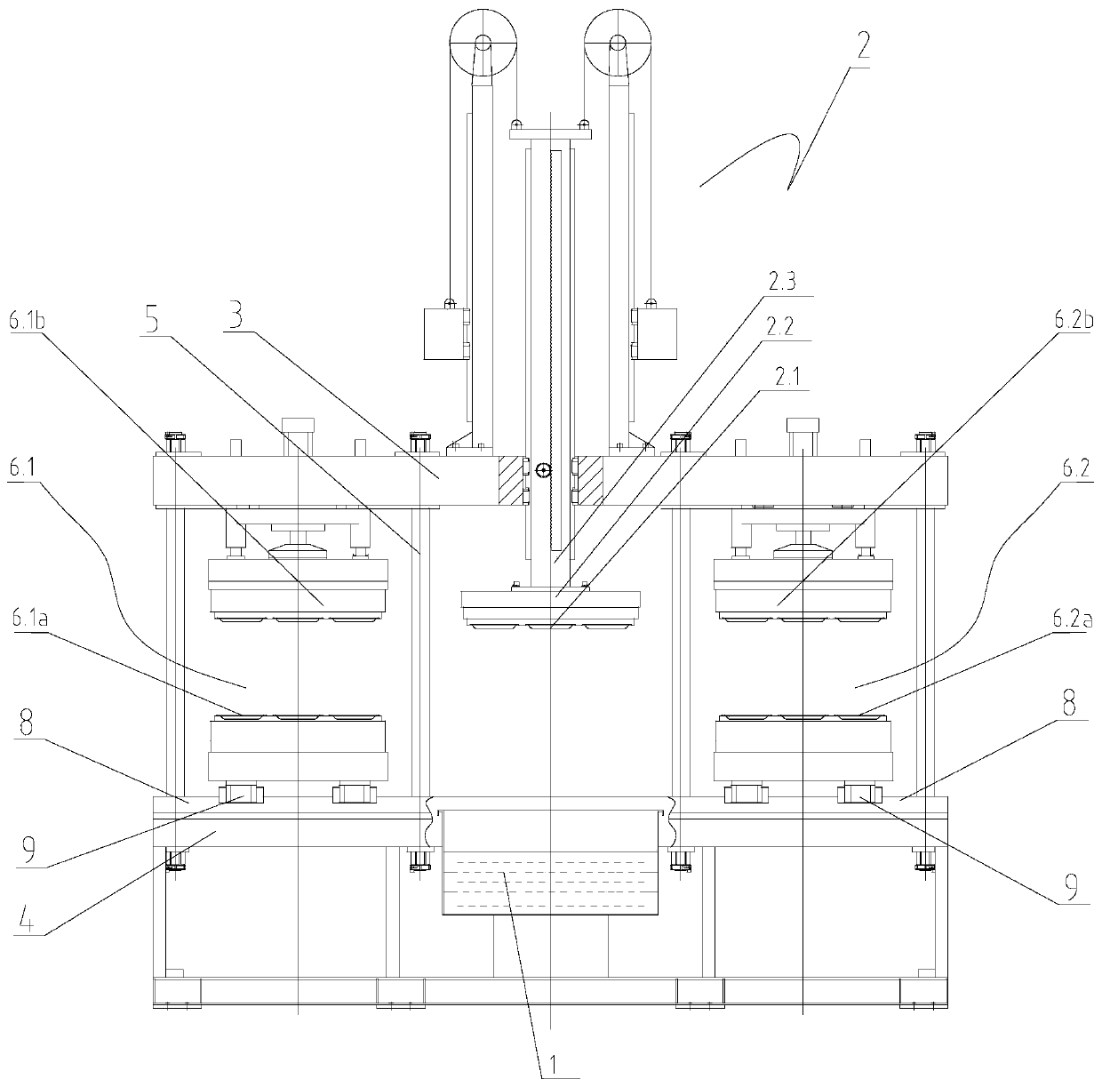
[0044] Such as figure 1 As shown, the plant fiber molding machine includes a slurry tank 1, a suction filter forming device 2, and a frame. Slurry is housed in the slurry tank 1, and frame is made up of pull bar 5, lower frame 4 and upper frame 3, and pull bar 5 fixes upper frame 3 on lower frame 4, makes upper frame 3 and lower frame 4 Keep a certain distance; the slurry tank 1 is arranged in the lower frame 4, the suction filter forming device 2 is above the slurry tank 1, and the suction filter forming mold 2.1 of the suction filter forming device 2 can move up and down vertically, when the suction filter forming device 2 The suction filter forming mold 2.1 moves down vertically to the slurry in the slurry tank 1, the suction filter forming mold 2.1 vacuums the slurry in the slurry tank 1, and the suction filter forming mold sucks the wet billet in the slurry for a certain period of time in the suction filter forming mold Formed on the top, the suction filter forming mold ...


PUM


Abstract

The invention relates to a method and device for manufacturing a plant fiber product comprising paper pulp in a molding mode. According to the technical scheme, the suspension type suction filtrationforming method for plant fiber molding forming comprises the following steps of: 1) a suction filtration forming die vertically move downwards from a set height, and suction filtration forming is carried out in slurry in a slurry tank; 2) the suction filtration forming mold drives the wet blank to vertically move upwards to leave the liquid level of the slurry tank, and stops moving after rising to a certain height; (3) the wet blank in the suction filtration forming mold is sent out and delivered to the next procedure to be dried; and (4) the step (1) and the step (3) are repeated, so that plant fiber molding forming is continuously carried out. In the suction filtration forming process, slurry can be more evenly distributed on the surface of the suction filtration forming mold, and the suction filtration forming mold can accurately, stably and rapidly enter or move out of the slurry.

Description

technical field [0001] The present invention relates to a method and device for making plant fiber (abbreviated as plant fiber; hereinafter the same) products including pulp by molding; it is suitable for making disposable planar or non-planar plant fiber molded products, especially suitable for making one-time Non-planar paper products; such as plant fiber tableware, plant fiber trays, plant fiber industrial products shockproof pads and packaging trays or boxes, disposable non-planar plant fiber decorative three-dimensional wall panels (or plant fiber three-dimensional wallpaper or pulp molded three-dimensional wallpaper), exquisite small-angle plant fiber industrial packaging tray and box products, flat and three-dimensional products made of starch and plant fiber mixture by molding, or starch and plant fiber mixture as raw material by molding Foamed planar and three-dimensional products produced by molding methods, as well as all disposable plant fiber molded products, are ...

Claims


Application Information

Patent Timeline
Patent Type & Authority Applications(China)
IPC IPC(8): D21J5/00
CPCD21J5/00
Inventor 郑天波郑卓
Owner EURASIA LIGHT IND EQUIP MFR
Why Eureka
Try Eureka