Photography light panel reflector clamp

a technology for reflectors and light panels, applied in lighting support devices, lighting and heating apparatuses, instruments, etc., can solve the problems of not providing such function in conventional clamps, and achieve the effect of convenient and quick mounting, easy and quick mounting, and reduced damage to photography light panel reflectors

Active Publication Date: 2016-09-29
LINCO
View PDF7 Cites 2 Cited by
  • Summary
  • Abstract
  • Description
  • Claims
  • Application Information

AI Technical Summary

Benefits of technology

[0011]With the turning clamp set and the groove provided by the present invention, the photography light panel reflector can be easily and quickly mounted with the rod member, and the damage to the photography light panel reflector can be minimized.
[0012]Comparing with the conventional mounting methods and the conventional clamps, the engagement provided by the present invention between the photography light panel reflector and the rod member is more stable, and the mounting process is also easier. On the other hand, when compared with the conventional spring clamps, the photography light panel reflector clamp provided by the present invention is less likely to damage the photography light panel reflector during the mounting process. When compared with the conventional two-pieces clamps, the photography light panel reflector clamp provided by the present invention does not require precise alignment and therefore the mounting process thereof is easier. The clamp provided by the present invention is also less likely to fall off. In addition, the clamp provided by the present invention can also be used to mount electric wire sets. The conventional clamps do not provide such function.
[0013]Comparing with US Application Publication 2004 / 0226903A1, when the user fits or takes off the photography light panel reflector, the first turning knob doesn't need to be taken off from the mounting face, and the user doesn't need to make an orifice on the photography light panel reflector. The photography light panel reflector can be easily and quickly mounted with the rod member.
[0014]Comparing with U.S. Pat. No. 5,634,619, the groove doesn't need any inwardly disposed screws. And the turning clamp set preferably includes a first turning knob defining an abutting surface with an area greater than so as to cover the groove and compressing against the segment of the flange. So the contact area among the first turning knob, the photography light panel reflector and the groove is greater than the contact area between the screws and the article. The damage to the photography light panel reflector can be minimized. And the photography light panel reflector can be easily and quickly mounted with the rod member.

Problems solved by technology

The conventional clamps do not provide such function.

Method used


Image

  • Photography light panel reflector clamp
  • Photography light panel reflector clamp
  • Photography light panel reflector clamp

Examples


first embodiment

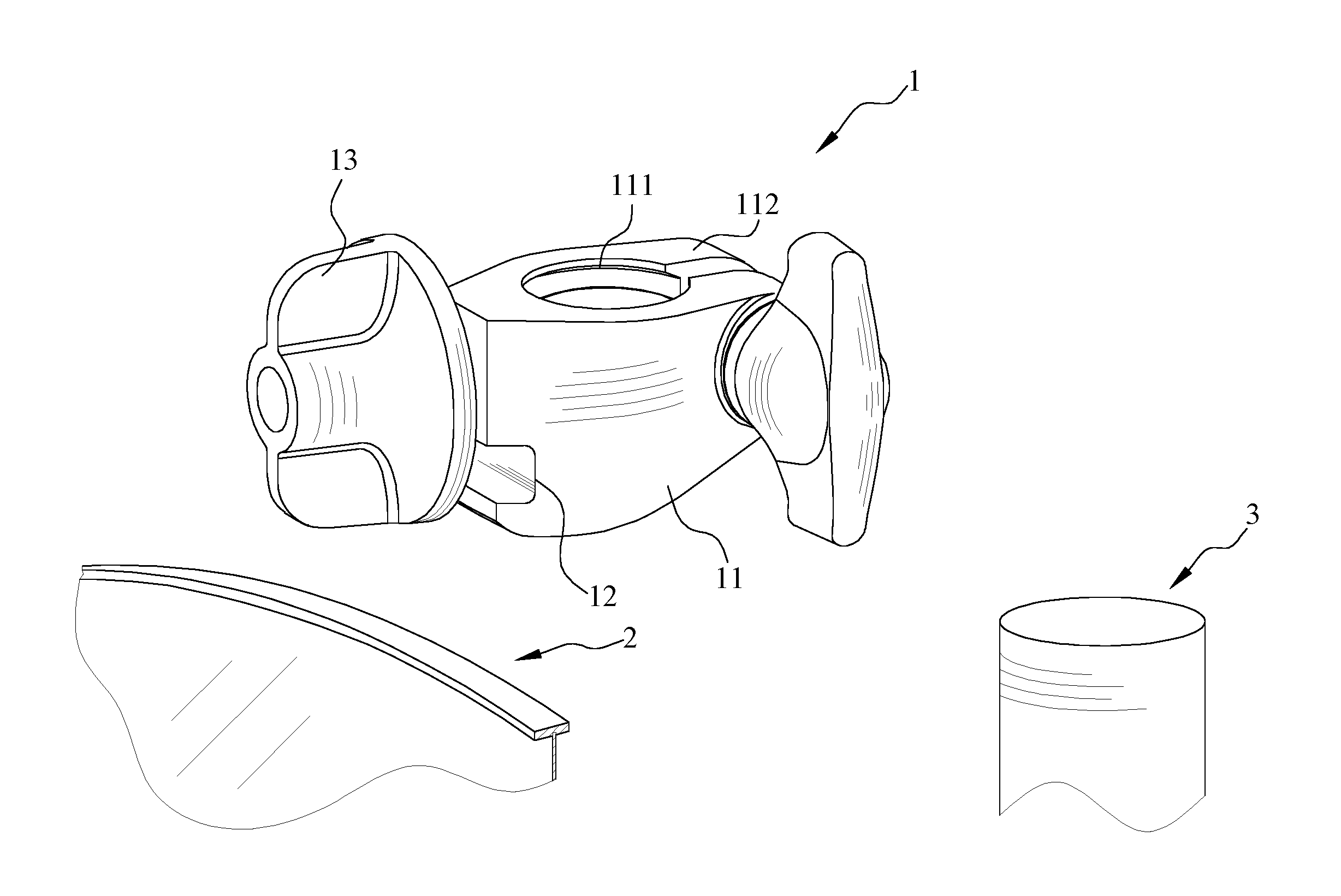
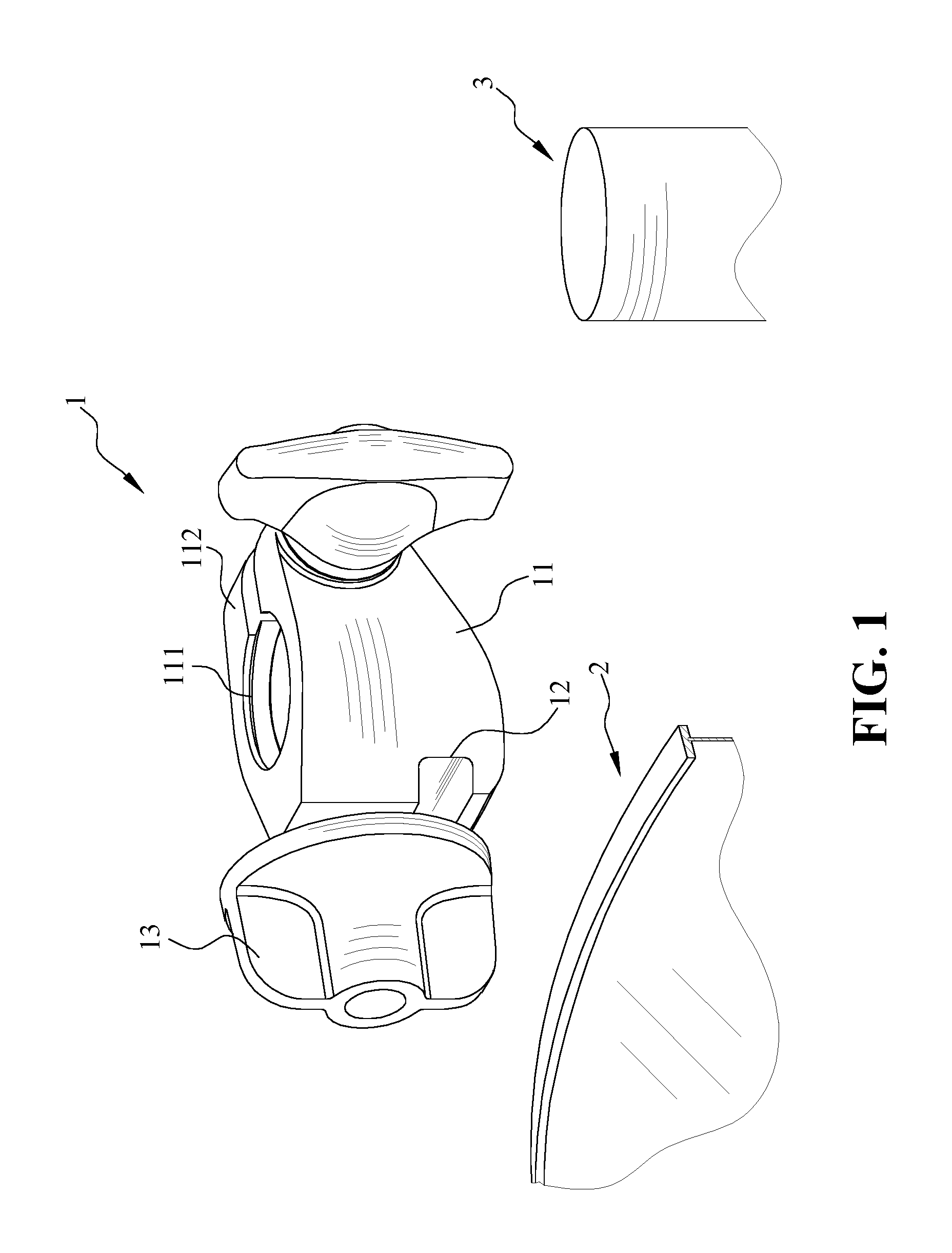
[0029]FIG. 4 is a perspective view showing the photography light panel reflector clamp according to the present invention. In addition to clamping the photography light panel reflector 2, the present invention can also be used to mount wire sets 4 of lighting devices or other electronic equipments. As shown in FIG. 4, wire sets 4 can be fitted inside the groove 12, and can be restricted inside the groove 12 by tightening the first female turning knob 131.

[0030]FIG. 5 is a perspective view showing the photography light panel reflector clamps according to a second embodiment of the present invention, which is also a preferred embodiment of the present invention. In the second embodiment, two photography light panel reflector clamps 1 are used to mount the photography light panel reflector 2. As shown in FIG. 5, the photography light panel reflector clamps 1 are mounted on any two opposite ends of the photography light panel reflector 2, and then the photography light panel reflector c...

third embodiment

[0031]FIG. 6 is a perspective view showing the photography light panel reflector clamp according to the present invention. As shown in FIG. 6, the turning clamp set 13 of the present invention can also be a first male turning knob 133. A first tapped hole 134 is disposed on the mounting face 113 next to the groove 12. The first male tuning knob 133 is engaged with the first tapped hole 134 so as to fix the segment of the photography light panel reflector 2 between the groove 12 and the first male turning knob 133.

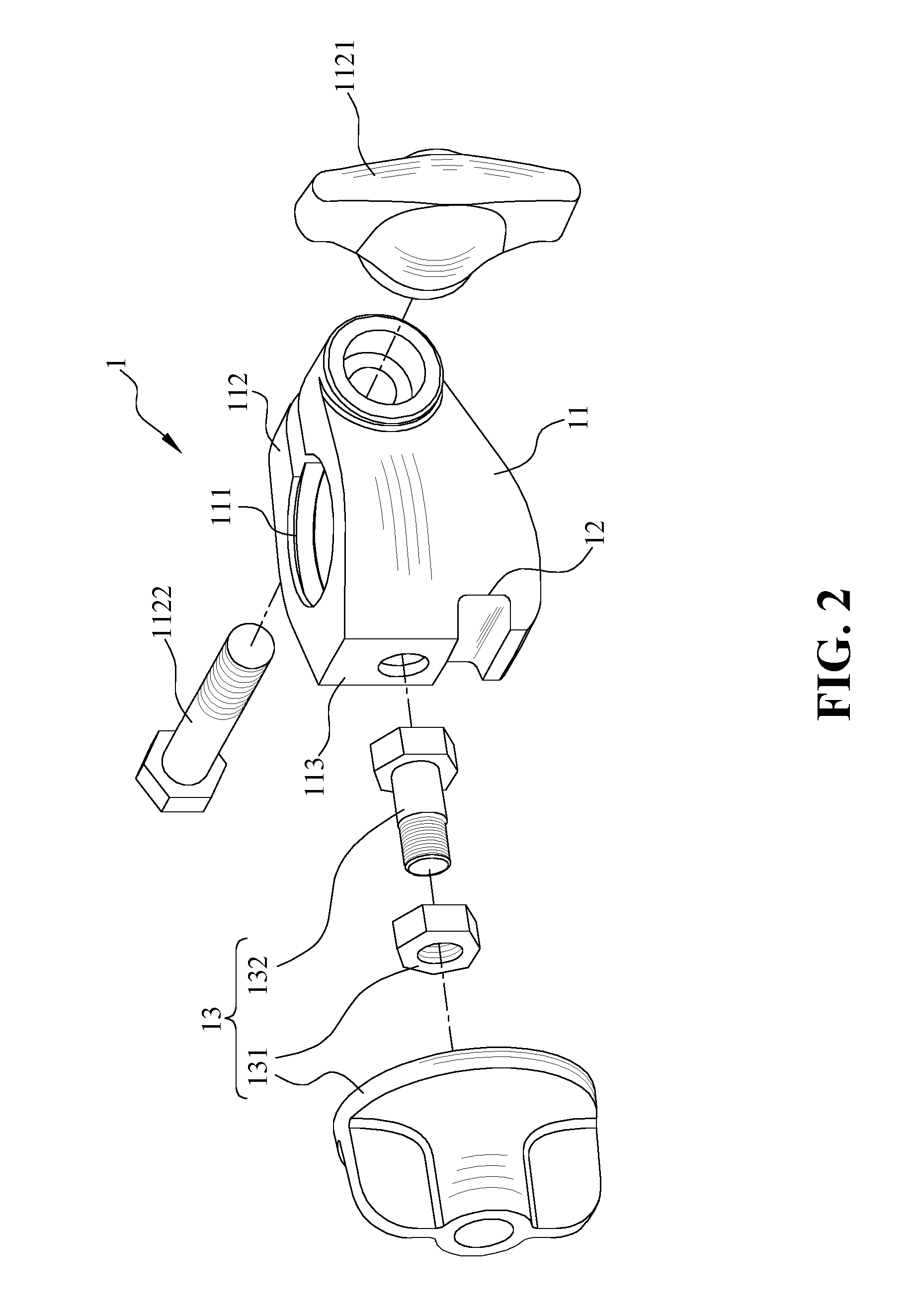
[0032]According to the third embodiment, the mounting portion 112 further includes a second male turning knob 1123. A fitting hole 1124 is disposed on a side of the mounting portion 112, and a second tapped hole 1125 is disposed on another side of the mounting portion 112 corresponding to the fitting hole 1124. The second male turning knob 1123 is put through the fitting hole 1124 and is engaged with the second tapped hole 1125, thereby mounting the rod member clamping seat...


PUM


Abstract

The present invention provides a photography light panel reflector clamp for mounting a photography light panel reflector with a rod member. The photography light panel reflector clamp of the present invention includes a central member, a groove and a turning clamp set. A rod member clamping seat is disposed on the central member, and a mounting portion is disposed at an opening of the rod member clamping seat. The groove is formed across a mounting face on a side of the central member, and the turning clamp set is disposed on the central member next to the groove. A flange of the photography light panel reflector has a segment fitted in the groove, and the turning clamp set is utilized to fix the segment of the flange of the photography light panel reflector in the groove with the photography light panel reflector clamp.

Description

CROSS-REFERENCE TO RELATED APPLICATION[0001]This application is a continuation-in-part of U.S. patent application Ser. No. 14 / 139,795, filed on Dec. 23, 2013, which is incorporated herewith by reference.BACKGROUND OF THE INVENTION[0002]1. Field of the Invention[0003]The present invention relates to a photography light panel reflector clamp used in photographing and video recording. More particularly, the present invention is a photography light panel reflector clamp with a turning clamp set, which can be used to mount a photography light panel reflector with a rod member.[0004]2. The Prior Arts[0005]Photography light panel reflector is a type of auxiliary lighting tool used to reflect light, and is frequently used in photographing and video recording. When photography light panel reflectors are used during photographing or video recording, the colors of the photographs or videos are more enriched, and the photos or videos can be presented in a more stereoscopic manner. Photography l...

Claims


Application Information

Patent Timeline
Patent Type & Authority Applications(United States)
IPC IPC(8): F21V17/16G03B15/06F21V17/12
CPCF21V17/162G03B15/06F21V17/12F21V21/088F21V7/18F16M11/00F16B2/065G09F2007/1813G09F2007/1817G09F7/18G09F2007/183G09F15/0037G09F15/0025G09F2007/1804
Inventor LIN, CHIEN-TING
Owner LINCO
Why Eureka
Try Eureka