Photo display hanger and kit

a technology for hanging racks and photos, applied in the field of supports, can solve the problems of adding no “feng shui, mars wall or door, unsightly conventional hooks, etc., and achieve the effect of high degree of flexing without breaking and easy replacement of displays

Inactive Publication Date: 2011-04-21
MORRISON DAVID J
View PDF11 Cites 3 Cited by
  • Summary
  • Abstract
  • Description
  • Claims
  • Application Information

AI Technical Summary

Benefits of technology

The photo display hanger and kit of the present invention incorporates a support hook(s). The hook is fabricated from a flat sheet of material. The material may be transparent and is capable of a high degree of flexing without breaking. Double-sided tape is employed to mount the sheet on a flat, vertical surface, such as a wall or door. The sheet is adapted to neatly present a display. The display may take the form of a photograph, an advertisement, a message, or the like. The display can be easily changed without cau...

Problems solved by technology

Unfortunately, conventional hooks are usually unsightly and add no “feng shui” to the surrounding area.
Furthermore, conventional hooks are usually “permanently” mounted using a screw fastener or the like, which mars the wal...

Method used


Image

  • Photo display hanger and kit
  • Photo display hanger and kit
  • Photo display hanger and kit

Examples


second embodiment

FIG. 7 shows the invention wherein plural hooks 40 are disposed along a bottom edge 40a of transparent sheet 42. A decorative frame (not shown) is configured to be disposed on sheet 42 in the same manner as described above relative to sheet 12. This embodiment is especially useful for hanging an array of keys thereon.

third embodiment

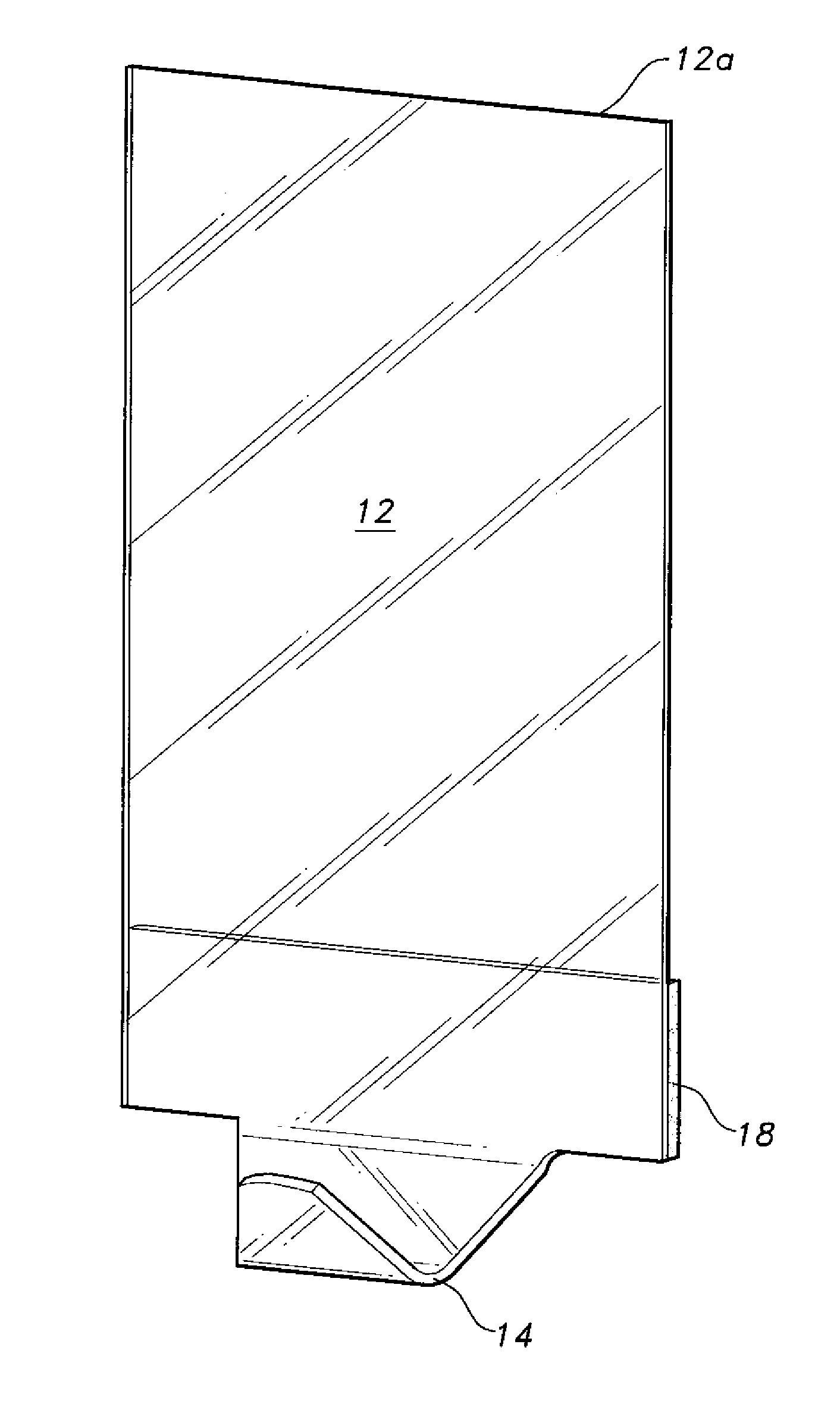
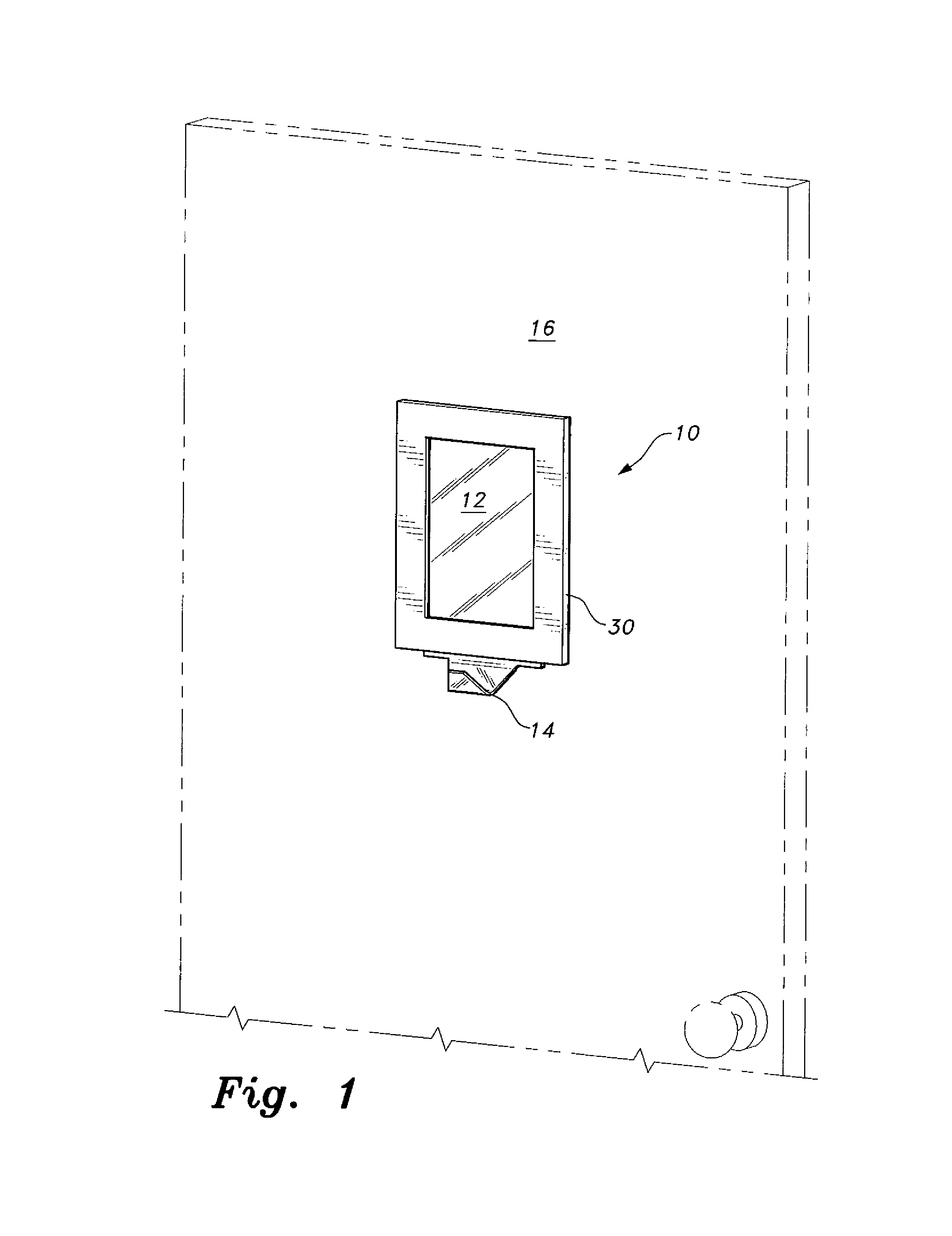
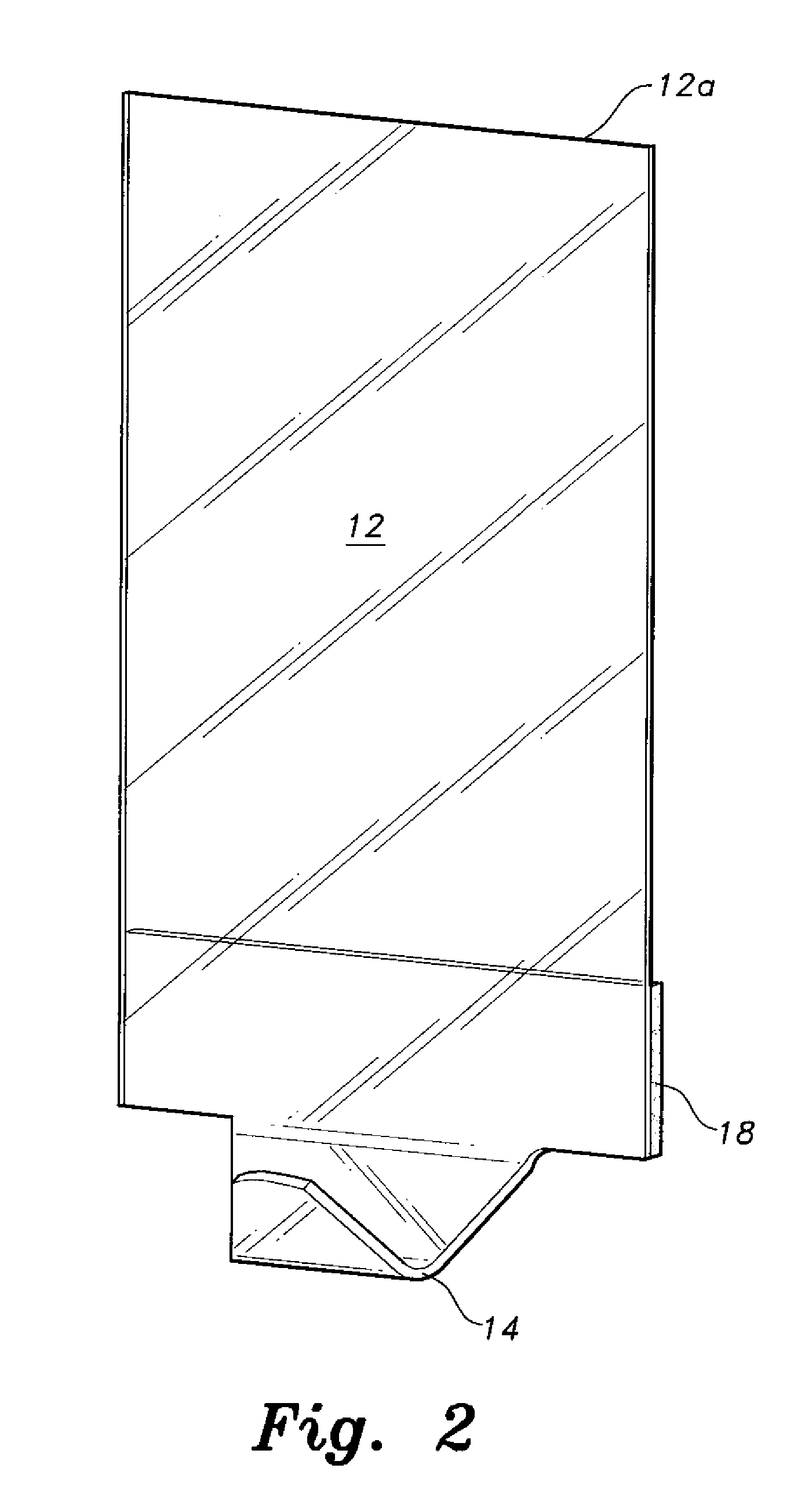
FIGS. 8 and 9 are illustrative of the invention that incorporates a single, unitary sheet 50 provided with a hook 52 at the lower end thereof. The front surface of sheet 50 is designed with a cavity 54 therein. Cavity 54 is adapted to receive a display item 22, the display item 22 being nested within the cavity 54. A transparent window 56 is removably press-fitted into cavity 54 to retain the display item 22 in the cavity 54. Double-sided adhesive strips 18 are employed on the rear surface of sheet 50 to removably mount the sheet on a vertical surface. An opening 58 is formed through sheet 50 to facilitate the removal of window 56 when it is desired to change the display 22. Although illustrated as rectangular, it is obvious that sheet 50 can be fabricated in other configurations, if desired. Sheet 50 can be transparent, translucent or opaque.

fourth embodiment

As best seen in FIG. 10, the invention is provided with a unitary sheet 60 having a base 62. Respective sides 64 extend perpendicularly upward from the base 62, forming a fork defining a cavity 66. A single leg 68 extends medially downward from base 62. A hook 70 is positioned on the front surface of leg 68. As in the embodiment described immediately above, a display item 22 is sized to nest within cavity 66 and a transparent window 72 is press-fitted into cavity 66 to retain the display item therein. Sheet 60 can be transparent, translucent or opaque.

FIGS. 11 and 12 illustrate an embodiment of the invention wherein the sheet member 80 of the photo display is fabricated to have peripheral dimensions (length and width) to enable the sheet member to fit into conventional mailing envelopes. A photograph display area is centrally disposed in the sheet. Die-cut hooks 82 are disposed in the bottom edge 80a and coincident with the plane of sheet member 80 for mailing purposes. Double-sided...


PUM


Abstract

A photo display incorporates a support hook(s) as a display adjunct. The hook is fabricated from a flat sheet of material. The material is capable of a high degree of flexing without breaking. Double-sided tape is employed to mount the sheet on a flat, vertical surface such as a wall or door. The sheet is sized to neatly present a display item. The display item may take the form of a photograph, an advertisement, a message, or the like. Other forms of the photo display employ adjuncts that permit easy mailing of a photograph or the like and support for displaying the photograph.

Description

BACKGROUND OF THE INVENTION1. Field of the InventionThe present invention generally relates to supports, and particularly to a photo display hanger and kit that incorporate adjunct support structure therewith.2. Description of the Related ArtThe use of hooks for supporting objects, such as garments, hats, keys, umbrellas, etc., is commonplace. The hooks are conventionally mounted on walls or doors in the home or office. Unfortunately, conventional hooks are usually unsightly and add no “feng shui” to the surrounding area. Furthermore, conventional hooks are usually “permanently” mounted using a screw fastener or the like, which mars the wall or door.Mailing that special photograph of a wedding, birthday, bar mitzvah, etc. to favorite people can be a hassle in that the photograph must be wrapped in a protective covering and then housed in a separate mailing envelope. Furthermore, when received, a frame must be located before the photograph can be properly displayed. The art would cer...

Claims


Application Information

Patent Timeline
IPC IPC(8): B65D27/00
CPCA47G1/06A47G1/0633A47G25/0607G09F1/12B42D15/027F16B45/00G09F1/00B42D5/025F16B45/008
Inventor MORRISON, DAVID J.
Owner MORRISON DAVID J
Why Eureka
Try Eureka